Hen-Delta 6 Meter Copper Pipe Antenna
Hen-Delta 6 Meter Copper Pipe Antenna.PDF
Hen-Delta 6-Meter Copper Pipe Antenna
By Chris Prioli, AD2CS
Illustrations from the August 2022 issue of ARRL’s QST magazine.
By Chris Prioli, AD2CS
Illustrations from the August 2022 issue of ARRL’s QST magazine.
|
Whereas I have “built” several wire antennas, there really is not much to the building process with them. You start with a center connector, add the wire by way of insulators from the hanging system, add the antenna wires and tie them into the center fitting, add insulators at the wire ends, and finish off with UV-stable rope. Of course, the antenna needs a little bit of adjustment, but the build is really that simple. Not so with the 6-meter Hen-Delta copper pipe antenna (Figure 1) presented in the August 2022 issue of QST magazine. This antenna is also quite simple to build, don’t get me wrong… it is not rocket science, but it does require a little bit of thought and planning.
The antenna’s active components are the copper pipes, and its support structure is comprised of the plastic pipe parts. The QST article called for the use of 1-1/2” schedule 40 PVC pipe and fittings, but due to cost and ready availability, I went with 1-1/2” schedule 40 black ABS drain/waste pipe and fittings instead. The assembly requires a ten-foot length of 1-1/2” plastic pipe, sixteen inches of which will be cut off for use in forming the cross arms. That leaves one hundred and four inches of vertical support pipe for the antenna. The distance from the centerline of the cross arms to the lower anchor point of the copper antenna pipe is specified as sixty inches. The cross bar TEE and its associated fittings account for three and a quarter inches of support frame length. If the one hundred and four inch length of support tube is inserted into the bottom of the assembled TEE, and we measure sixty inches down from the cross bar centerline, the antenna tube anchor point will be fifty-six and three-quarters inches from the bottom of the assembled TEE. With three-quarters of an inch of pipe engagement into the bottom of the TEE, the anchor point will be fifty-six inches below the bottom of the TEE, and thus forty-eight inches above the lower end of the support pipe. If the support pipe is installed into an embedded length of 2-1/2” plastic EMT electrical conduit set into the ground, and if the Hen-Delta support pipe is allowed to settle down with its bottom at grade level, the top of the antenna will be approximately thirteen and seven-eighths feet high. Of course, the antenna height can be increased by simply raising it up higher in the conduit support pipe and clamping or pinning it there. To that end, and also |
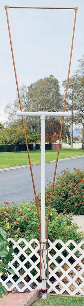
Figure 1 : The Hen-Delta Antenna
|
to help to keep the Hen-Delta from rotating in its conduit mounting pipe, I advise making a saw cut into the upper end of the plastic conduit pipe, centered across the conduit and about four inches deep. This will allow clamping of the plastic support pipe in place in the embedded conduit via a pair of stainless-steel worm-drive hose clamps, set about three inches apart over the saw kerfs.
So let’s talk about the small parts used in assembling the support frame. As I said earlier, I used black ABS waste/vent pipe for this build, which I will refer to henceforth as simply ABS. The only ABS TEE that I could easily locate that was symmetrical in form with a centered “stem” was a clean-out TEE, which has the stem port threaded internally. To connect this TEE to the ABS pipe, I used a male pipe thread to ABS adapter, whose plain end is the same OD as the 1-1/2” ABS pipe. Thus, to connect the adapter to the pipe, I used an inch-and-a-half ABS coupler. This accounts for the extra “assembled” length of the TEE mentioned above. Figure 2 illustrates the general planform of the Hen-Delta antenna and its support system.
The QST article talks about cutting a 5/8” wide by 2-1/2” long slot in the outer ends of the cross bar tubes. No mention is made, however, of the best way to accomplish this task. Here is what I did. I started with the crossbar pipe, cut to length, placed in my V-block on the drill press table. I then drilled a 1/4” hole through the pipe, two and a half inches from the end of the pipe. Using a step bit, I enlarged the hole on each side of the pipe to its final size of 5/8”. Next, I drew pencil lines from the edge of the hole along the pipe to its near end, doing this on both sides of the hole, so as to define the slot. Then, with the holes at top and bottom, the pencil lines on top, and the pipe clamped in position extending out of the V-block, I used my band saw to cut the slots, meeting the drilled holes. As the top and bottom were cut simultaneously, only two cuts were required on each pipe section to complete the task. When cementing the cross bar pipes into the TEE, be sure to orient the pipes so that the slots are at the top and bottom of the cross bar, as the copper pipe must fit into these slots. The copper pipes are held in place in the slots by the ABS caps that will be cemented in place later.
Each of the ten-foot lengths of 1/2" copper pipe are bent at about two feet from one end, so that they will form the Delta shape when the short straight lengths are placed parallel to each other. The upper end of each of these pipes is flattened, as are the ends of a thirty-three inch length of pipe that makes the top cross-tube of the Delta. It is important that the flattened ends of the cross-tube are in the same plane, as are the flattened upper ends of the verticals. It is best to flatten the ends of the verticals after the bend is made, as the pipe will then lay flat on the work surface in the plane in which the flats should be made. I chose to coat the inside of the ends of the copper pipes with liquid electrical tape immediately before flattening those ends, in the hope that this might seal the ends of the tubes against water and insect entry. The lower ends are left open and round, as they are connected together via a pair of copper pipe elbows and a 2-1/2 inch long length of the 1/2” copper pipe, which are all sweated in place together.
Each of the flattened pipe ends gets a 1/4” hole drilled through the flattened area (Figure 3). The cross-tube is then fastened to the two verticals via 1/4-20 x 3/4" stainless-steel capscrews with flat washers and self-locking nuts. Note that all of the hardware used in this antenna is of the stainless-steel type, so assume that any hardware referenced herein will be of that type, even if not specifically described as such. To aid in the electrical connectivity of the cross tube with the vertical pipes, I added an externally-toothed 1/4" lock washer between the flattened ends on assembly.
The 2-1/2-inch length of pipe gets a 1/4" hole drilled through it, perpendicular to the plane of the Delta. This hole indexes with a similar hole drilled through the ABS support pipe sixty inches below the horizontal centerline of the support frame cross bar. The two pipes are then secured together via a 1/4-20 x 3” capscrew with flat washers and a self-locking nut. Whereas self-locking nuts are not strictly required where the flattened pipes are joined, a self-locker is required where the copper pipe is secured to the support pipe. This is because tightening a standard hex nut and lock washer there would likely crush the ABS pipe before the nut was tight enough, or had compressed the lock washer properly.
Assembling the Delta onto the support pipe involves starting out with the Delta low on the support pipe, with the wide part of the spread above the notched cross bars of the support frame. Then, raise the Delta along the support pipe, guiding the sides of the Delta into the notches as the copper pipe assembly is raised, then aligning the 1/4" hole in the Delta’s lower cross pipe with the 1/4” hole in the support pipe. Insert the three-inch washered capscrew through the holes and secure it with a washer and a locknut. Once the Delta is secured to the support pipe, cement the ABS caps onto the cross bars to lock the Delta into place there.
Connection of the feedline to the antenna is accomplished through the use of an insulated strip of material (Figure 4) onto which a pair of 1/2" copper pipe straps have been mounted. The pipe straps are installed over the parallel segments of the Delta pipe. The RG-58 cable is secured to the straps on either pipe segment by terminating the coax center conductor and its shield wire into #10 ring terminals. The straps are mounted to the insulting strip with 10-24 x 1” machine screws with flat washers and self-locking nuts. The inner machine screw on each strap gets a coax connection via a ring terminal under the nut and washer. I used a sheet of 1/8” thick phenolic sheet from which I cut a 5-1/4” x 1/2" strip for this job. The QST article called for the strip to be 5-1/8” wide, but I opted for a little more support for the outboard mounting screws. The antenna’s SWR is adjusted by sliding this strip up or down the pipe segments as necessary before tightening the nuts completely.
In a similar manner, a resonant frequency adjuster is made of another strip and two more 1/2" copper pipe straps, this time out of a conductive strip. The material used in this case was a sheet of dual-sided copper-clad PCB substrate, 3/32” thick and cut to the same 5-1/4” x 1/2" size. The frequency adjuster is installed to the parallel pipe segments below the SWR adjuster (Figure 5). As with the SWR adjustment, the resonant frequency is adjusted by sliding the clamps up or down the pipes. In reality, the resonant frequency is set first, and then the SWR is adjusted.
The RG-58 cable referred to above should be approximately ten feet in length, with the #10 ring terminals on one end and with an appropriate connector for your system on the other end. Most builders will install a PL-259 plug there, while others might opt for an SO-239 terminating connector or a BNC connector. The antenna requires the use of a simple 1:1 choke balun which can be constructed either by installing several Mix 61 toroidal ferrites onto the coax below the antenna, or by wrapping six turns of the standing length of the coaxial cable around the support pipe below the antenna and securing them there with zip ties. An STL file is available for a 3-D printable bobbin which will fit on the support pipe and contain the six wraps of coaxial cable. This is the method that I chose to employ, as it avoids the need to leave the fairly large loop in the coax that would be required in order to allow movement of the SWR bar all the way up the parallel pipes if necessary. I simply set the SWR bar all the way up the pipes and then installed the bobbin right under the antenna. When I then slid the SWR bar into its final position, the bobbin would slide down the support pipe and keep the coax snug. For long feedline runs, transition to a less lossy cable such as RG-213 or LMR-400 at the end of the RG-58 pigtail.
If needed to disguise the true purpose this antenna, banners or flags can be attached to it without overly affecting the performance of the antenna. Thus, this is a good alternative for those hams who may be under some sort of antenna restriction.
Let’s talk performance now. I am going to borrow some of this, including the illustrations, from the August 2022 issue of QST, which is the source of the inspiration for this project. According to that article… ”The top of the Hen-Delta is wider than the bottom, which pushes the effective center of radiation upward. This reduces ground loss and ground sensitivity, which improves performance when ground mounted. Maximum radiation moves upward because of the proximity of the out-of-phase and equal-amplitude currents in the Hen-Delta's lower conductors, thus canceling radiation from the vertical antenna section. The electromagnetic (EM) wave from a Hen-Delta, therefore, emanates mainly from the horizontal top section, making it horizontally polarized.”
As also stated in the QST article, the antenna has about 6dBi of azimuth gain, as is evident from the radiation pattern illustrations. The radiation is effectively perpendicular to the plane of the Delta. Figure 6 shows the 500kHz SWR curve for the antenna, centered on its resonant frequency of 52MHz. Figures 7 and 8 are the azimuthal and elevation radiation patterns, respectively. In both of those figures, the blue line indicates the one-foot pattern while the violet line indicates the ten-foot pattern. As is evident from these patterns, the antenna’s pattern is somewhat similar to that of a vertical in elevation and to a dipole in azimuth. The Hen-Delta is a good compromise and a better-than-average performer for the springtime 6-meter QSO’s that some hams chase.
The build was a fun build, with just enough challenge to make it interesting. The most challenging part of this project was the bending of the copper pipes to get two symmetrical angles in the end. I am not quite sure why this was so, but only that it seemed to be more difficult than I expected it to be. The rest of the job was sheer mechanics and no problem at all. I would rate this project as an “entry-level” job that most beginners should be able to handle. Because the 6-meter band is available to all license classes, this project should have wide appeal.