AD2CS Test Bench
Troubleshooting Techniques
Electronic Tool Tips
WWW.AD2CS.COM
Troubleshooting Resources
AD2CS Quansheng UV-K5 (8) Handheld Radio Review.PDF
Lightweight Paddle Set For CW Operators
By Chris Prioli, AD2CS - [email protected] - www.ad2cs.com
By Chris Prioli, AD2CS - [email protected] - www.ad2cs.com
|
This article is a slight departure from my normal writing, in that that the topic at hand here is a description and round-about endorsement of a product. On tap as the subject of this article is the cwmorse.us “Red Lightweight Double Paddle With Steel Base” (Figure 1). On their website, cwmorse.us describes this paddle by stating that it is an… “…Ultimate Lightning Fast Double Paddle Morse Code Key. Super Smooth Action With Dual Precision Self Lubricating Nylon Bearings. Solid Brass Contacts With Stainless Steel Fasteners & Nickel Plated Steel Spring. All Soldered Braided Copper Wire Connections.” I was introduced to this paddle by fellow GCARC member John Zaruba Jr, K2ZA. It did not take me long to read through the small amount of literature available about the paddle set. I then made the decision to purchase one and to see what all the positive press was about. |

Figure 1 : cwmorse.us Paddle Set

Figure 2 : Paddle With Cover Removed
|
Now… I am not very capable as regards CW. I am still only learning the requisite skills - both memory and physical - to be able to become competent. However, one of the factors in developing the physical muscle memory to permit Morse competency is having a good, solid, and consistent key system on which to learn. If the key environment is constantly changing, your muscle memory will develop much more slowly as you will be forced to continually re-acclimate yourself to the changing key conditions.
While each CW operator develops his or her own preference as to key type, the paddle system has become quite popular in today’s amateur radio CW circles. Part of the reason for this is the ability to quickly and easily inject opposite morse characters into the middle of a continuing stream of base characters. For example, if the operator is sending the string “091”, it would be coded as :
– – – – – – – – – • • – – – –
or
dah dah dah dah dah dah dah dah dah dit dit dah dah dah dah
or
dah dah dah dah dah dah dah dah dah dit dit dah dah dah dah
using standard International Morse Code. When sent via a paddle, this is accomplished by holding the right lever for the proper count to send the dahs, lifting as needed for the spaces. Then, when it is time to insert the two dits, simply tap the left lever twice with a lift between them.
Another example might be seen in sending the single character “Q” which consists of the code string dah dah dit dah, and is sent by holding the right lever for a four-count, while also tapping the left lever once at the count of three. This will inject a dit between the second and third dahs.
Another example might be seen in sending the single character “Q” which consists of the code string dah dah dit dah, and is sent by holding the right lever for a four-count, while also tapping the left lever once at the count of three. This will inject a dit between the second and third dahs.
|
When the new paddle arrived, I immediately set about getting a “feel” for the new device. It is well-weighted, so it stays put on the desktop, using four rubber feet to help keep it from sliding around. The connection to the radio is via a 3.5mm (1/8”) TRS jack (Figure 3), so if your radio uses a 1/4” key jack, an adapting cable or a plug adapter will be required. The paddle is comfortable under the fingertips, and is fully adjustable as to travel and tension. Adjustment is made via a trio of stainless-steel socket-head machine screws (Figure 4). One of these screws is mounted through the left-hand lever and is the rear-most of the adjustment screws (when viewed from the lever end of the unit). That particular adjustment screw controls the spring tension exerted upon the levers. Tightening the screw increases the spring tension, making the lever action stiffer. The remaining two screws are mounted, respectively, through the left-hand and the right-hand adjustment stop blocks, and their tips are directly in contact with the side of the lever toward which each screw is pointing. These screws adjust the lever travel by changing the at-rest positions of the levers. |

Figure 3 : Connection End View

Figure 4 : Adjustment Screw Arrangement
|
The looser the screw, the greater the travel. As a nod to “attention to detail”, the Allen wrench required to make adjustments to this paddle set is included with the unit, and it has a convenient storage location machined into the plastic upper base of the paddle, which is visible in the Figure 3 illustration.
Due to the nature of the paddle design, the three wires of the TRS jack are connected as follows :
- Tip (T) to right lever (dah) via the RED wire;
- Ring (R) to left lever (dit) via the YEL wire; and
- Sleeve (S) to common via the GRN wire.
This is the standard configuration for a right-handed paddle setup. However, if your radio uses the opposite configuration, you will need to place your radio’s paddle setting in reverse mode (if available) or else use an adapting cable that has the wires crossed to accommodate your radio’s key/paddle circuit.
The base of this paddle is a steel plate 1/2” thick and three inches square. All edges and corners are killed so that there are no sharp aspects to this base. The remainder of the unit, apart from the TRS jack, the wire, and the hardware, is all of the 3-D print manufacturing process. Even the cover that snaps on over the works is a 3-D printed item. When we think of 3-D printing as a manufacturing method, we often think of the product as being of lesser quality somehow. That is clearly not the case as regards this paddle. All of the parts are cleanly made and they all fit - and work - together quite well.
The paddle is available in several different colors, including army green, black, blue, green, grey, indigo, orange, purple, red, and yellow. The price for the basic paddle is $42.95, while the price of the paddle with the steel base is $64.95. The base is available as an accessory for $24.95. The web address for the sales site is https://cwmorse.us.

|
For those who are able to interpret it, there is a message in the label (Figure 5) that is affixed to the top cover of each paddle sold by this company… only it is actually printed in Morse. It says “USA” – the location in which all of this company’s products are proudly manufactured.
|
W2MMD Clubhouse Test & Repair Bench : Coaxial Cable Tester
By Chris Prioli, AD2CS - [email protected] - www.ad2cs.com
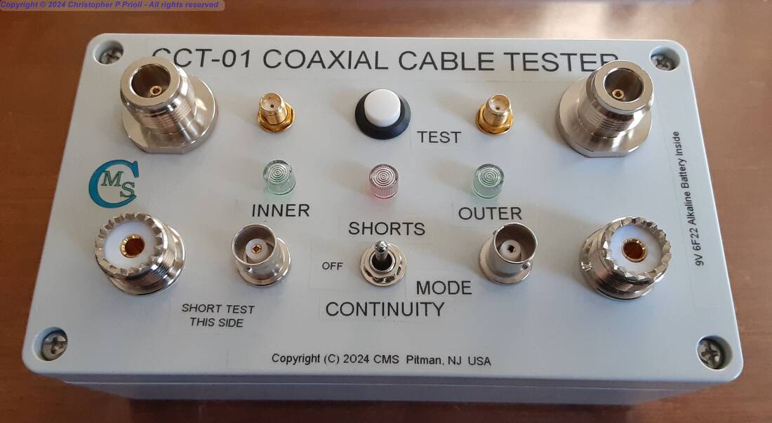
I am very pleased to announce that I have just added a new piece of equipment to the W2MMD Clubhouse arsenal on the test and repair bench. The new tool is a multi-connector-type coaxial cable tester that will test cables of several types and of any length for continuity on the outer shield braid and on the inner center conductor, as well as testing the cables for shorts between the braid and the center conductor.
The tool indicates the results of the two-stage testing process via LED's on the front panel. The test procedure instructions are labeled on the unit, which is extremely easy to use.
This device will test cables with SMA, BNC, UHF, and N connectors, in any combination of those connector types. It is compact, portable, and completely self-contained. It is powered by a standard nine-volt alkaline snap-top battery, which should have an extensive service life due to the very limited current drawn during the testing of the cables.
I am fully open to suggestions for additional test equipment that may be suitable for the Club and for the T&R bench. Please feel free to pass any such comments or suggestions on to me, as well as any comments on the new cable tester.
By Chris Prioli, AD2CS - [email protected] - www.ad2cs.com
I am very pleased to announce that I have just added a new piece of equipment to the W2MMD Clubhouse arsenal on the test and repair bench. The new tool is a multi-connector-type coaxial cable tester that will test cables of several types and of any length for continuity on the outer shield braid and on the inner center conductor, as well as testing the cables for shorts between the braid and the center conductor.
The tool indicates the results of the two-stage testing process via LED's on the front panel. The test procedure instructions are labeled on the unit, which is extremely easy to use.
This device will test cables with SMA, BNC, UHF, and N connectors, in any combination of those connector types. It is compact, portable, and completely self-contained. It is powered by a standard nine-volt alkaline snap-top battery, which should have an extensive service life due to the very limited current drawn during the testing of the cables.
I am fully open to suggestions for additional test equipment that may be suitable for the Club and for the T&R bench. Please feel free to pass any such comments or suggestions on to me, as well as any comments on the new cable tester.
Electronic Tool Tip #1 - FRP Tube Pin Straightener
|
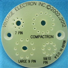
I came across this tool while searching for an obscure vacuum tube on ebay.com one day, and I decided then to buy one and to give it a try-out. I was pleasantly surprised by the results. The tube that I was searching for had a Compactron base, and I had used that term in my search query, which is how I ended up finding this handy tool. The tool is a vacuum tube pin straightener, designed to straighten and align the pins of some of the most popular vacuum tube base types out there, namely the miniature seven-pin, the miniature nine-pin, the |
|
miniature ten-pin, the Magnoval, the Noval, and the Compactron bases.
The tool is fabricated from a piece of one-quarter-inch thick FR4 fiberglass board material, and it is precisely machined as to its general form and its pin openings. Each of the pin openings is wider at the tool surface, where the pins get inserted, and then the holes taper down to the final pin diameter, bringing misaligned pins into shape quickly and easily.
There are a pair of countersunk holes in the body of the tool, useful for mounting the tool to a bench top for stationary use, where it would not take up much space, being a mere two and a half inches in diameter.
Unlike some other tube pin straighteners out there, this one does not have vertical guides for the tubes, meaning that both large-envelope more modern tubes and miniature-envelope vintage tubes will fit the tool equally well.
The tool costs $29.95 (USD) from Vintage Electron via their eBay storefront, where this vendor has a 99.9% positive rating over almost 16,000 transactions. The vendor reports that they will give one of these tools free with each order over $250 from their storefront, where they deal with all kinds of vintage electronics parts and components.
I much prefer this tool to the newer series of same-priced 3-D printed straighteners offered by other vendors on the auction site. I believe that this tool, due to its machined holes rather than printed holes, will be more accurate. I also believe that the tool’s material of construction will make it more durable than the 3-D printed versions.
Go to ebay.com/itm/224424049020 to investigate this tool for yourself.
Electronic Tool Tip #2 - Vacuum Tube Puller
|
It is funny how you sometimes find a great idea when you are looking for something else. I was on ebay.com one day looking to purchase some NOS (New Old Stock or “Nasty Old Stuff”) vacuum tubes of the 12AU7 type, when my search for that tube number brought me to this little wonder. I have often struggled to remove vacuum tubes from down inside a host of other tubes, transformers, and capacitors, with little or noroom for getting a decent grip on the vacuum tube, which is slick and slippery glass to begin with. |
|
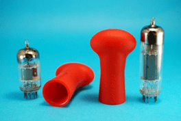
On occasion, I have even broken a tube or two trying to get them out under really tight space conditions. As a result, I was very quick to jump on this nifty tool when I found it. The illustration above shows two of these tools together with two vacuum tubes; the price discussed near the end of this article will get you a single puller.
The concept is quite simple. The tool is a molded pliable thermoplastic tube with a “flattened” mushroom profile and a closed dome at the upper end. To remove a vacuum tube, the tool is placed down over the top of the tube, and then the tube can be wiggled and pulled straight up and out. The tool is then easily removed from the vacuum tube by just pulling it off at a slight angle to break the suction.
It is an easy task to use the tool as an aid in the installation of the vacuum tubes back into the equipment chassis. Insert the tube into the puller, align the pins with the tube socket properly, and push the tube into place. To remove the tool from the installed tube, once again pull the tool off at a slight angle to the tube to break the suction.
This puller fits many of the miniature seven-pin, nine-pin, and ten-pin tubes, and is quite useful when space around the tube location is limited. I heartily recommend this tool to anyone who does more than just occasional vacuum tube removal and installation.
The tool costs $10.95 (USD) from spin4cards via their eBay storefront, where this vendor has a 100% positive rating over 15,500 transactions. Shipping was quite reasonable at $4.95 from Cicero, NY.
Go to https://www.ebay.com/itm/394061782564 to investigate this tool for yourself.
Electronic Tool Tip #3 - Lead Bending Jigs
|
Doing even the little things neatly and precisely is the hallmark of a craftsman, in any field or discipline. That extends to a simple thing like bending the leads of electronic components to fit properly into printed circuit board (PCB) locations designated for those components. It is not unusual for hobbyists or even professional electronics technicians to bend component leads freehand. Another option is to grab a pair of needle-nose pliers and use them to bend the component leads. While both of these methods work, and while both of these methods are widely used, I prefer to size and form the leads properly for the PCB hole spacing in use. |
|
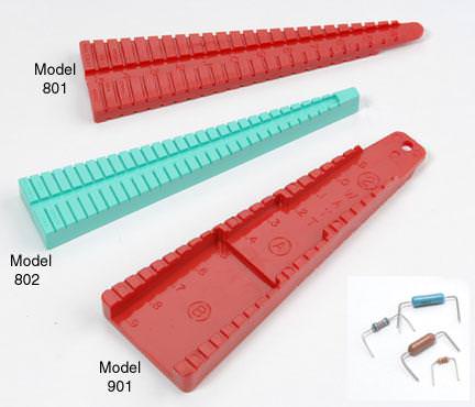
To that end, I have long used devices similar to those illustrated above. In fact, some of the jigs in my assortment are the same ones as those depicted in the illustration. Others? Well, I have had some of them for so long that I have completely forgotten when, where, or from whom I purchased them.
I have a total of six bending jigs in my assortment, each of them sized differently either for the component body sizes that they will handle, or for the spacing distances offered, with those distances being either metric or English dimensions. These things are handy! Can the job be done without using these jigs? Sure… but it is not as good a job as when the jigs are used. Components bent with the jig just fit! In addition, the contours of the jigs cause the bend radius of each component lead bent in the jig to be precise and in line with the standard bend radius limits typically defined by the component manufacturers. Further, there is no risk of nicking or damaging the component leads as is possible when using pliers to bend the leads.
The set shown above is available at $12.50 (USD) as a set, or individually at $4.80 each. They can be ordered directly from the manufacturer, Production Devices via their website, where they also offer telephone ordering of their products. The tools are USA made and the company is located in El Cajon, California.
Go to http://productiondevices.com/leadformingtools.html to investigate this tool for yourself.
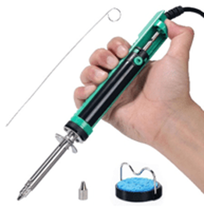
Electronic Tool Tip #4 - Desoldering Pump
|
Every electronics hobbyist will eventually find the need to desolder components, whether from point-to-point “dead bug” wired devices or from a printed circuit board (PCB). It will also come to pass that the solder wick, the squeeze bulb, and the stand-alone plunger pump will no longer fill the bill. The reason for this is that by the time that you remove the soldering iron and properly place the vacuum tool on the joint, the solder will have solidified again. What is needed is the ability to suck the solder out while still heating it. Not every hobbyist will have the need or even the budget for a high-dollar electric vacuum pump type of desoldering tool. This is where this pump comes in. The tool is a combination of a soldering iron and an integrated plunger pump in a single assembly. |
|
Use of this tool very quickly becomes familiar and routine. The only problem that I had was making myself remember to point the tip of the tool upward while resetting the plunger, so as to avoid forcing solder balls down into the tip of the tool.
The tool works best on PCB’s, but it performs acceptably on dead bug wiring as well. It will take some getting used to, but the “heating while sucking” action is the ticket. As the user’s needs grow, it may be appropriate to move up to a higher-level desoldering pump, but for most hobbyists, this tool is a good choice.
The barrel lifts directly off the frame of the iron for cleaning of the accumulated waste solder from within the barrel. Re-assembly is simple - just align the end of the barrel with the opening in the base of the iron’s frame, and then press the barrel down onto its locating tabs in the upper end of the frame.
The desoldering pump, Yihua model #929D-V, comes complete with a stand, and extra tip, and a cleaning tool used to keep the tip clear.
The tool shown above is available at $39.99 (USD). It can be ordered directly from the Yihua store at www.amazon.com, where the many high-quality offerings of this company are showcased. Yihua manufacturers a wide line of soldering and desoldering tools and equipment, suitable for anyone from the hobbyist to the professional.
Go to https://www.amazon.com/gp/product/B094ZCRXMN to investigate this tool for yourself.
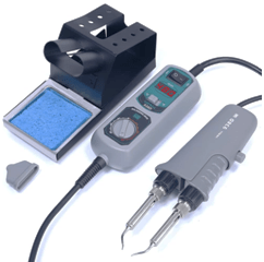
Electronic Tool Tip #5 - Hot Tweezers
|
From time to time, it becomes necessary to solder - or desolder - SMD devices to or from a printed circuit board (PCB). -While this can often be done with a pencil-type standard soldering iron with a fine tip, it is often much more convenient to use a pair of “hot tweezers” for this task. Many companies make hot tweezers, but I am a fan of the Yihua products. I already own a Yihua 948-II soldering station and a 929D-V desoldering pump iron. This tool was a logical addition to my armory of soldering equipment. The use of a hot tweezer becomes especially useful when the chip sizes get smaller. The |
|
larger chips are more easily handled with a standard pencil iron, but the tiny SMD devices demand a better alternative, and this may just be it.
The tool consists of a fixed iron with a specialized bent tip, and an opposing movable spring-loaded iron with its tip bent to mate with that on the fixed iron. The opening angle of the hot tweezer is adjustable for convenience of the user.
The hot tweezers, Yihua model #938D, comes complete with a stand and a cleaning sponge, as well as a protective cover for the (cool) tips. The unit is temperature-controlled, with the adjustment made via a potentiometer on the control unit located on the tweezers cord. I have ordered replacement tips directly from the manufacturer via an e-mail exchange.
The tool shown above is available at $104.99 (USD). It can be ordered directly from the Yihua store at www.amazon.com, where the many high-quality offerings of this company are showcased. Yihua manufactures a wide line of soldering and desoldering tools and equipment, suitable for anyone from the hobbyist to the professional.
Go to https://www.amazon.com/gp/product/B078NS2HZ8 to investigate this tool for yourself.
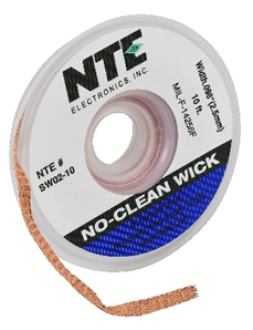
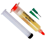
Electronic Tool Tip #6 - Solder Wick & Flux
|
When it comes to removing solder from a joint or a PCB, sometimes using solder wick is the quickest and easiest way to go. This is especially true when working with SMD component installation and removal, and with cleaning the PCB pads after an SMD component has been removed. Solder wick is a flat braided length of fine copper wire strands, available in various widths and also in various spool sizes. The better solder wicks are pre-impregnated with rosin flux, but even they can stand an occasional boost of additional flux to really get the solder flowing up the wick. The braid is laid in place on the solder to be removed, and heat from a soldering iron is applied to the braid, moving the iron on the braid, and sometimes moving the braid itself, as necessary to absorb the desired solder from the joint. Solder wick must be clean in order to do its job, so for best results, cut off the used portion frequently as you work. Rosin flux can be added before the wick is applied, or it may be applied directly onto the wick braid. Either method will get the job done. I prefer the braid marketed by NTE Electronics of Bloomfield, NJ as their part number SW02-10, which is a ten-foot length of the 0.098”-wide braid on a convenient plastic dispensing spool. It is of a high quality and it always does the job without the strands separating as some other brands will do. I rarely need to add additional flux with this brand of solder wick, but with some other brands, flux must be added every time it is used, almost as if the wick has no flux in it at all. One brand of rosin flux that I like is ChipQuik part number NC191. This product comes in a capped syringe and includes the plunger, a dispensing tip, and a cap for the dispensing tip. I remove the plunger and the dispensing tip from the syringe after each use, and store the whole shooting match in its original heavy-gauge zipper-type plastic pouch, with the original syringe cap put back in place on the business end of the syringe. I also highly recommend the use of a more free-flowing liquid rosin flux such as the GC Electronics 10-4202 Liquid Solder-Flux. I typically purchase this in a brush-cap bottle. The part number cited above will get you a two fluid ounce bottle of this flux. Note that clean-up of rosin flux and its residue can most easily be accomplished through the use of 99.9% isopropyl alcohol (IPA), scrubbing with a toothbrush as needed to get the stubborn areas clean. |

|
These items are widely available online, from suppliers ranging from Amazon and Jameco to Mouser and Digikey. Pricing is approximately $10 (USD) for the ChipQuik rosin flux, $20 (USD) for the GC Electronics rosin flux, and $7 (USD) for the solder wick, all as described above, from Digikey.
Go to www.digikey.com to investigate these items for yourself.
Go to www.digikey.com to investigate these items for yourself.
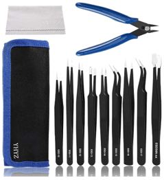
Electronic Tool Tip #7 - Static Free Tweezers
|
When handling electronic components, it is necessary to get into the habit of ensuring that the devices are protected from the discharge of static electricity. Static discharge can immediately destroy many components, especially any semiconductor devices of the CMOS type. With the miniaturization of electronics devices and components, it becomes necessary to use tools to lift, handle, and manipulate many components, particularly SMD components. This is where a good set of anti-static tweezers comes into play. The tweezer set shown here includes high-quality non-magnetic stainless-steel tweezers that are anti-static and non-corroding. This particular set offers nine different tweezer types plus a pair of fine cutters, a wiping cloth, |
|
and a carrying pouch to keep everything together, and is called their nine-piece set. Also available are two seven-piece sets and individual tweezer models. I use my ESD-11 tweezer from this set literally on a daily basis, and I have found them to be quite durable.
The tweezers aid greatly in the placement of SMD parts onto the printed circuit board (PCB), and the back end of the tweezer is useful for holding the device in place while soldering is being done. Just a little bit of downward pressure on the chip keeps it from walking away while the soldering process occurs.
Tweezers like these are a tool item that any electronics hobbyist should not be without. They are useful for a wide array of tasks, like plucking one particular resistor out of a container or pile of components, or for aligning the holes in a PCB with the mounting holes in an enclosure. A favorite trick of mine is placing washers onto screw threads in poorly accessible locations, and then starting a hex nut on the threads. This is done by inserting the long narrow tip of the ESD-11 tweezer into the center of the hex nut, and then letting the tweezer open to hold the nut on the end of the tweezer. Next, bring the tip of the tweezer into alignment with the end of the screw, and then squeeze the tweezer to allow the hex nut to slide down onto the end of the screw. Then simply reach in there with the tip of a screwdriver, with the tweezer still in place to serve as an axle, and turn the hex nut to begin the thread engagement. A lock washer, for example, can be placed onto the screw threads in the same manner before the hex nut is put into place.
This set is available online from Amazon, at a price of $13.99 (USD) plus shipping if you are not an Amazon Prime member. Of course, the governor has to get his share, so tax will also be applied.
Go to https://www.amazon.com/dp/B07JMBGL3W to investigate this item and its companion sets and individual pieces for yourself.
Electronic Tool Tip #8 - Lighted Helmet Magnifier
|
Working with miniaturized components can be a challenge in more ways than one. Right now, however, we are going to discuss the vision aspect of miniature components - or maybe even not-so-miniature items. Not very long ago, my vision was failing badly due to cataracts and glaucoma. As a result, I had lens replacement surgery for the cataracts, and I had stents implanted at the same time for the glaucoma. Now, some five months later, my vision has stabilized at the acuity level that it will be from here on out. After wearing eyeglasses for sixty years for extreme myopia, I can now see great distances perfectly well. It is for the close at hand that I now need some help. |

|
Most of the time, I find that help in the form of two different pairs of reading glasses, each having a different diopter level. I swap them off depending upon how close I need to see. However, I have found a great tool that helps immensely, in a one-size-fits-all variety.
I am talking about the helmet-style lighted magnifier shown above. This unit is worn like a welding helmet, and it flips up out of the way the same way that a welding helmet does when it is not needed. What is great about this unit is that it is illuminated with three super-bright LED’s that can be aimed and can be set to either one of two brightness levels as needed. The best thing of all about this tool is the fact that it uses interchangeable main magnifying lenses, which can be used singly or in any combination of two lenses simultaneously. The lenses supplied include 1.0X, 1.5X, 2.0X, 2.5X, and 3.5X magnification levels. The unit also has a small auxiliary lens at 8.0X that can be swung into place for those really hard to see things. The instruction sheet provides a table that lists the effective magnification and focal lengths of the various lens combinations, which range from 1.0X up to 14.0X and from 35mm (at 14.0X) out to 500mm (at 1.0X). The main lenses snap into holders that can be individually swung up out of the way when not needed.
The magnifier includes a rechargeable (and replaceable) 3.7V 300mAh lithium polymer ion battery, part number 602030, which is readily available from various online sources. From fully discharged, recharging the battery takes about an hour and a half, and a full charge lasts about eight hours. The unit as sold includes a micro-USB charging cable, a set of three static-free stainless steel tweezers, a cleaning cloth for the lenses, and a storage case to hold the lenses when not in use.
This magnifier is available online from Amazon, at a price of $35.99 (USD) plus shipping if you are not an Amazon Prime member. However, in the last week, the Amazon availability of this item has changed, leading me to point out the existence there of an almost identical but less-expensive alternative unit. This option comes in at a price of $28.04 (USD). Of course, the governor has to get his share, so tax will also be applied.
Go to https://www.amazon.com/dp/B0BKQXP9Z1 to investigate the original item, or
to https://www.amazon.com/dp/B0BL2QT8D4 to investigate the second item for yourself.
Electronic Tool Tip #9 - Multifunction Cable Tester
|
Every now and then, I come across an idea that is so good that I wish that it had been my idea in the first place. In this case, I had been looking to build just such a tester as the one discussed here, but I realized that I could not do the job nearly as well as the manufacturer of this device did it without breaking the bank on the project. I was looking to build a cable tester that could test multiple configurations of cables, regardless of what connector types were on the opposite ends of the cable. In other words, I wanted to be able to test a cable that had, for example, a 6.35mm TRS plug on one end and an XLR connector on the other, or maybe, a 3.5mm TRS plug on one end and a 6.35mm TRS plug on the other end. Whatever the arrangement, I wanted it to be seamless, and to test and report on a wire-by-wire basis when I had continuity and if I had wire-to-wire shorts or wire-to-shell shorts. While this tool does not test all possible cable types, it does test enough of them to merit a place on my workbench. It is much easier and quicker to test with this tool than with an ohmmeter or continuity tester. |

|
The CT-20 Cable Tester from MFL does an amazing job for the cost of the unit. It has the ability to test cables having connectors including 3.5mm TRS, 6.35mm TRS, 3-pin XLR, 5-pin XLR, RCA, 3-pin DIN, 5-pin DIN, 7-pin DIN, 8-pin DIN, mini 4-pin DIN (S-video), 4-pin Speakon, powerCON, RJ-45, HDMI, USB-A, USB-B, micro-USB, and/or banana plugs, in any combination of connectors on a given cable. The unit is powered by a single 9V “transistor radio” snap-top battery. A battery test function is available on the front panel via the main rotary control.
That rotary control on the front panel steps through each wire of a given cable, indicating continuity by an illuminated LED. Additional LED’s lit indicate a short to that wire or to GND (shell). Pins 11 through 20 of an HDMI cable are tested by use of a momentary switch that is held down while stepping through those pins, after the first ten pins have been tested. A chart on the back panel of the tester shows the wire connections for the various plug types.
Sure… the device has its limitations. For example, it does not test USB-C or some of the other USB appliance connector variations. I am currently looking for an easy way to add some of those connector types to the unit, but no promises yet on that score. But… for what the unit cost to purchase, it does a creditable and convincing job on the cables that it will test.
This tester is available online from Amazon, at a price of $60.99 (USD) plus shipping if you are not an Amazon Prime member. Of course, the governor has to get his share, so tax will also be applied.
Go to https://www.amazon.com/gp/product/B0972J2ZR9 to investigate this item for yourself. NOTE: At the time that this was written, Amazon showed “out of stock” on this item, but they have since gotten it back into their inventory. Meanwhile, AliExpress also offered this item, if you don’t mind doing business with them. I have had some good luck the few times that I bought from AliExpress, so I am not absolutely opposed to buying from them again. Just Google “CT-20 cable tester” and it should come up.
Electronic Tool Tip #10 - Infrared Thermometer
|
From time to time, I will encounter an electronic device that is not functioning quite as it was designed. For example, I might come up against a radio in which one of the amplifier stages is kaput, which is causing a more generalized failure to be evident. Not being one who takes kindly to “busy” work, I am usually interested in a reliable shortcut that will help to resolve the issue at hand. One such “shortcut” is a pistol-grip infrared thermometer. I chose the IRT207 from General Tools (Figure 1) mainly because it was what was in stock at the neighborhood Lowe’s store when I was looking to buy one of these devices. That fact notwithstanding, I would now make that same buying decision even when considering a varied group of candidates. The IRT207 is compact, easy to use, goes almost forever an a single 9-volt snap-top battery, and displays its readings clearly on a backlit LCD panel. The operational specifications for the IRT207 are shown in Figure 2. Note that the field of view is fixed at a ratio of 8:1, which means that the scanned surface area of the target object will grow at that ratio. For example, at 8 inches from the working face of the thermometer, the scanned area target spot will have a diameter (ø) of one inch. At a 16 inch distance, that scanned area “spot” will now have grown to ø 2”, and then to ø 3” at a 24 inch distance from the thermometer to the target surface. |


|
The IRT207 is selectable as to °C or °F, managed by a push of the left-hand switch on the thermometer display panel. In addition, the aiming laser can be selectively active or inactive, again by a mere button press, this time to the right-hand switch on the display panel of the thermometer.
To use the IRT207, simply point the sensing end of the thermometer towards the surface or object of interest and pull the trigger, holding the trigger until you register the temperature of the target. The aiming laser can be used to help ensure that the unit is sampling the correct or desired point. When the trigger is released, the temperature displayed will be “held” in the display until the display blanks out, which event will occur at about seven seconds after trigger release.
An infrared thermometer is extremely useful in diagnosing weak or under-performing semiconductor devices. Such devices will generally run colder than their neighboring devices. Conversely, semiconductors that are flowing excessive current will generally run hotter than their neighbors.
Excess current through any resistance will produce heat. This heat can be used to locate and identify circuit problems.
I am not saying that the thermometer is some sort of magic wand that will solve all of your diagnostic woes. I am saying, however, that the infrared thermometer is a valuable asset in your diagnostic tool set, and that thermal exploration can be a key process in fully inspecting a piece of electronic equipment.
This thermometer is available online from Amazon, at a price of $37.99 (USD) plus shipping if you are not an Amazon Prime member. Of course, the government has to get its share, so tax will also be applied. Point your browser to https://www.amazon.com/General-Tools-IRT207-Temperature-Detector/dp/B00377BSU4 if you want to investigate this item for yourself.