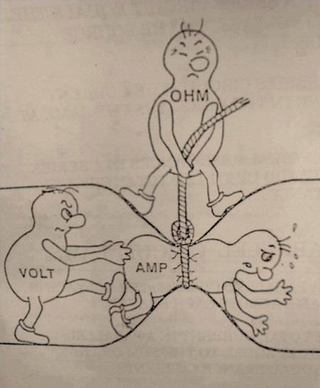
The Elmer's Shack
"The Elmer's Shack" is the brainchild of our very prolific writer Cory Sickles, WA3UVV. The idea behind it is to try and encourage a number of our experienced members to become Elmers, in the verbal sense, to our readers that could use the information provided. We have members that have experience in RF, DXing, digital modes, antennas, soldering, computers, contesting, and many other disciplines within amateur radio. This section is an open invitation for them to share their knowledge and experience with those who merely have an interest in amateur radio, are fully licensed, or somewhere in between.
|
The Money Bands, and “all those others”
By Jim Wright, N2GXJ
I was reading an article about Brian Justin, WA2ZMS, who just completed contacts on 29 ham bands. 29 ham bands? Wow! I didn’t even realize there were that many! When we operate field day, we tend to use what, like 6 bands? What are all these other bands? You probably already know. I needed a refresher. Follow along as I grab a copy of the latest US Amateur Radio Bands, and check out what these might be.
18 bands up to 1.2 GHz
Turns out there are now 18 bands up to the 1.2 GHz band, and another 11 above that. Setting those 11 bands above 1.2 GHz aside for a moment, what are these 18 other bands? And which are you equipped to operate on? Let’s check our radios, and start counting them up. Which am I missing?
I checked my radios. For many operators, like me, there’s 2 Meters, and 70 centimeters on our hand held HT or car radios. I use them when I’m traveling about town. As you know, your club, the GCARC, operates a System Fusion repeater on the 2 Meter band at 147.180 MHz from a Pitman water tower location. A 70 cm repeater can also operate out of that location. Technician privileges give you access to both of those bands. Ok, that’s 2 bands so far.
Main bands on HF
If you’re privileged to be able to play on HF, then there are the “money” bands of 80 Meters, 40 Meters, 20 Meters, 15 Meters, and 10 Meters. You can get on these popular bands with most HF radios, using reasonably sized antennas. Do I call them the “money” bands because this is where the HF action is to score points during radio contest weekends? Or is it because of this natural affliction we hams develop, where we find ourselves needing to spend money to upgrade equipment again and again, to better compete on these bands? Whatever you call these bands, that’s 5 more, for a total of 7 bands so far. What others?
WARC bands
Some HF radios have access to the “WARC” bands. There are 3 of these bands - 30, 17, and 12 Meters. Some may recall when these bands were not part of amateur radio. However, you’d have to be getting up there in age for that to be the case. These became part of amateur radio in 1979. In the United States, we’ve had privileges on the WARC bands since the early 1980’s! Counting the years since then on your fingers? Yea, let’s not and say we did. Ok, that’s 3 more bands, total of 10 bands so far.
Magic Band
Let’s count 6 Meters. Technically, 6 Meters is above the HF band, though you can get it included in some multi-band HF rigs. There are also some hand held radios that offer 6 Meters. 6 Meters is sometimes called the “magic band”. When the sunspot numbers are high (not now), I am told it can be amazing.
Most of the time though, 6 Meters is “line of sight”, similar to 2 Meters. But sometimes, often in the summer, crazy sporadic-E skip can happen, offering long distance contact opportunities with very little power required. Also, meteor scatter communications is available on this band, day and night. Some people really like 6 Meters. When 6 Meters is hopping, I’ve heard of people calling in sick to the office to take advantage of the conditions, it can be that exciting when it opens up. Trouble is, you just never know when that is going to be, or for how long!
Old Top Band
160 Meters has traditionally been called the “top band”, but really isn’t anymore. There are a couple new bands more “top” than this “top band” now, but let’s talk about them later.
160 Meters takes an effort to operate on successfully. For starters, the wavelength is long and poses some antenna challenges. Using a favorite website for reference: www.chem.hawaii.edu/uham/antennas.html, you can see a half wave dipole on 160 Meters needs to be 254 feet long! Even a quarter wave vertical is difficult, without some kind of electrical shortening, as it needs to be 127 feet tall! There is also the matter of static crashes. Summer time lightning storms often cause considerable interference on the lower frequency bands, even at distance.
Still, for all its challenges, some people really like 160 Meters. They often put great effort (and money) into their stations, particularly the microphone systems, taking pride in having distinguished audio quality for those late night rag chew sessions. Ok, that’s two more bands mentioned, total of 12 so far.
Into UHF
In addition to being able to operate on 2 Meters or 70 cm, some hand held or base station radios are also capable of operating on one or more of these bands: 1.25 Meters (222 MHz), 33 cm (902 MHz), and/or 23 cm (1.2 GHz). As you may know GCARC recently installed a new BridgeCom repeater for 1.25 Meters at the Washington Township repeater location. It reportedly has great coverage even up into the Cherry Hill area. Ok, that’s 3 more bands. That’s 15 so far. Can you figure out yet what am I missing?
Channelized radio
60 Meters is one of them. Unlike other bands, this one is channelized with reduced power and other restrictions for use in the United States. Not all HF radios have this capability, and some of the older ones that do, don’t have the ability to operate on the channels currently authorized today. That’s 16. What are the other 2?
MF and LF, new bands
That exhausted the bands I was familiar with. But, it turns out there are two more. Last year, new “top” bands of 630 Meters (472 kHz, MF) and 2200 Meters (135 kHz, LF) have appeared on the ARRL’s chart of US Amateur Radio Bands, albeit with a number of restrictions. These restrictions include an effective radiated power limit of 1 Watt maximum on LF, or on MF if you are within 496 miles of Russia, and a unique requirement on either band to register first with the Utilities Technology Council. If I read this right, a power line carrier group may be able to deny your request to operate on these frequencies based on your location? I filled out the form for my QTH and submitted online tonight. I’ll let you know what happens.
If you thought there were technical challenges operating at 160 Meters, imagine 2200 Meters. A half wavelength for a dipole on 2200 Meters would be over a half mile long! No, I don’t have any equipment that can transmit on these bands. But I might be able to improvise some. And my old ICOM 7000 claims to have general purpose receive capability down to 30 kHz. So, here’s an offer. If any of you out there can transmit on these bands, and want to give a cross-band contact a try, I can give listening a try on one of these new bands, and call you back on HF. Let me know if want to give it a try!
Why Contest?
By Tony Starr WA2FZB
In the fall of 2015, I was installing a tower and antenna system for a station that I did not yet have. I had been QRT for close to 25 years, and was on my way to getting back on the air. My good friend Tom, N2SR, had given me 40 feet of Rohn 25g tower and got me a good deal on a Mosley Classic 33 antenna, and we were in the process of installing them, when I had to give some thought to what facets of this great hobby that I would be pursuing. At the time, I did not have a working rotator, but Tom had one that needed to be rebuilt. With winter approaching, we went ahead and put the antenna up anyway, figuring that I could always get the rotor up in the spring. Since Tom is an avid contester and DXer, he suggested pointing the antenna toward Europe. I told him to point it West, since at that time, I had no interest in working DX and thought I might like to work toward my WAS. He gave me an odd look, then swung the beam around on the mast, and locked it in place with a muffler clamp.
After the holidays were over, I was thinking that maybe I should start shopping for a used HF transciever to put on the air, when a late visit from Santa (actually it was my cousin Bob, W2RAD) landed a nice clean Kenwood TS-850 in my new "shack". Bob even brought a box full of accessories, cables, and other goodies that I needed to get on the air. I scrambled to borrow a 12 volt power supply, and on January 9, 2016, WA2FZB was back on the ham bands for the first time in a quarter of a century. All of the excitement of my Novice days came rushing back to me, and I even found that in a few weeks I could still copy code poorly at 13 wpm just like I did in my youth!
It only took me six or eight weeks to find out that I really did enjoy working DX after all, and I began to think that I should have let Tom point the antenna toward Europe like he wanted to. But I discovered something else, that stirred up excitement for me even more than the thought of working DX. I heard contesting going on during the weekends, and I wanted in. By then it was late February, the weather was starting to improve, and we were just a couple of weeks away from the ARRL DX SSB contest. Before that contest date came around, I was up on that tower with a pipe wrench turning that antenna toward Europe! I made almost 275 contacts that weekend and I have never looked back. Contesting is now my primary interest within the hobby.
But why contest? Many non-contesters wonder what is the attraction, and some are actually angered by the thought of wall-to-wall signals filling the bands for an entire weekend. But let's face it, contesting is a big part of the hobby, one which has pushed the state of the art for HF radios and antenna systems for decades now. Some of the best operators are contesters, and they are operating some of the best stations around. So just what is the attraction, anyway? Have you ever wondered, or were you curious about why you might want to pursue contesting?
Boiled down to its essence, contesting is just regular ham radio in a super fast, super concentrated form. Many of the things that average hams do during the week are done by contesters on the weekends, but at much faster speeds. Remember that I thought it might be nice to work on my WAS? How about working WAS in twelve hours? I actually did this in the November Sweepstakes last year, and came within one state of doing it again this year. Have you ever wanted to work toward DXCC? Avid DX contesters regularly do it in a weekend, sometimes on more than one band. These are examples of how contesting accelerates normal ham radio pursuits.
Perhaps you have wondered how effective your station is compared to other hams in your area. Contesting gives you a way to directly measure the performance of your station, and to see how much difference certain improvements will make. From one year to the next, you may replace that old tri-bander with the latest, computer designed work of aluminum art. A large increase in your contest scores over last year will go a long way toward convincing you that it was money well spent, even if the XYL does not think so. Contesting serves as a way to measure station performance.
I got my Novice license in 1976, my General in 1977, and my Advanced Class license in 1978, but I never went for my Extra Class back then, because I could not pass the 20 wpm code test that was a requirement in those days. I did get my Extra in 2016, but of course the code requirements had long been gone by then. But I can say with fair certainty that I could pass that 20 wpm test today, if there were one. So why am I much better at CW now than I was 40 years ago? CONTESTING! Specifically, CW contesting. There is nothing that has advanced my code copying ability better than operating in CW contests. The first time after I spent a weekend operating a big CW contest, and I went back to the regular CW bands the next day, I wondered why everyone was sending so slow. Contesting is excellent high speed code practice.
I am sure that you have felt the comeraderie that is an integral part of ham radio. In contesting circles, that comeraderie is magnified, but there is a twist, that comes from the competitive part of contesting. Your adversary may represent the competition, but you need his or her cooperation in order for both of you to succeed. This builds a sort of fraternity within the fraternity of ham radio that is very special, and very real. When you become a regular member of the contesting community you will recognize what I am referring to, and you may come to quickly appreciate it. In my less than two years of active contesting, I feel that I have been welcomed by the contesting community that exists within the main hobby.
Finally, there is the big reason, the obvious one. Contesting IS FUN! You only need to try it to find out for yourself. There are many who have tried out a state QSO party who had never before had an interest in contesting, and found out that they really enjoyed it. These can be a great introduction to contesting for the beginner, though I personally would suggest the North American QSO Parties, which are held in January and August. They are just twelve hours long, and are easy for beginners to jump into.
So why not contesting? Maybe you just need to give it try. But be careful, because it can be addictive! Looking forward to hearing you in the next one. CQ CONTEST!
John Fallows, VE6EY, of Calgary, Alberta, has published a series of articles on his website called
Noise Cancelers - RFI Survival Guide. The purpose of this information is to help hams and shortwave listeners lower their local HF noise floor and improve reception. You can view these articles at: http://play.fallows.ca/wp/series/noise-cancelers-rfi-survival-guide
If you saw my presentation at the November club meeting, you’re probably already on FT-8 by now. If not, there’s another reason you should be - 2018 is going to be the year of the Grid Square!
What’s a grid square? What’s FT-8? And why is 2018 the year of the grid square?
Fair questions. Let me start with the first. Grid squares are used by amateur radio operators, like you, to describe a location on Earth using just a few characters. It’s an ingenious scheme, coded using alternating pairs of letters and digits, to limit the amount of characters needed to transmit a location using voice, Morse code, or digital mode. Encoding the location like this allows it to be quickly and efficiently sent. This scheme was adapted in 1980 at a meeting in Maidenhead, England, giving it the common name of “Maidenhead grid squares”. Knowing your location, and the location of the station you are receiving, allows you to quickly approximate distance and bearing on a sphere between stations for contest logging and/or directional antenna pointing purposes.
So, how does the system work? Looking at a globe, and starting with the imaginary north-south “anti-meridian” line that goes from the South Pole up through the North Pole exactly on the opposite side of the planet from Greenwich, England, the 360 degrees of longitude around the world are divided into 18 bands, resulting in 20 degree longitude slices around the world. The first 18 letters of the alphabet are used in upper case to represent this longitude, from “A” to “R”.
Similarly, starting at the South Pole, and going up the 180 degrees of latitude up to the North Pole, 18 bands of latitude are created, each 10 degrees apart. Again, the first 18 letters of the alphabet in upper case are used to represent these latitude slices, from “A” to “R”. Thus, in just two letters, you can approximate a station’s location to within any 20 x 10 degree long-lat zone on Earth.
The Maidenhead agreement further divided each of long-lat zones into 10 bands of longitude and 10 bands of latitude, using the digits “0” to “9” to represent them, resulting in 2 x 1 degree “Maidenhead grid squares”. Putting this together, in just 4 characters (two letters followed by two numbers) you have an efficient scheme to approximate any longitude-latitude on Earth. By agreement, if further precision is needed, each of these are divided into 24 slices of longitude latitude to create “sub-squares” using the lower-case letters “a” to “x” (24 was selected to simplify manual calculation of degrees and seconds).
Here in Gloucester County, NJ, generally our Maidenhead locator is FM29, to 4 characters of precision. That’s all you need for most contests. To confirm your Maidenhead location, or to take this out to 6 characters (as is typically used in configuring software programs, like FT-8 in WSJT-X, and is used to help with antenna pointing when making exchanges at UHF/VHF frequencies and above), you’re encouraged to dust off the archives and check out page 11 of the June 2015 edition of Crosstalk. On this page you’ll find a short article titled “What’s a Maidenhead Grid Square?” with instructions on how to find your 6-character locator. Don’t have a copy laying around? No problem. Jeff, our historian and online publications guru has graciously made an online copy available. For convenience, a direct link is provided here: June 2015 Crosstalk
Now for the question, what’s FT-8? If you missed the presentation at our last club meeting, you missed a good one :) Thanks to Jeff again, it’s not a total loss. A copy of the presentation slides are provided below. Additionally, you can find an article on configuring for multiple users in FT-8 below and in the December 2017 Crosstalk.
Finally, so why is 2018 going to be the year of the grid square?
Ah, the answer to that is simple. Not heard of this yet? The ARRL is making it so with a new year-long operating event that starts 00:00 UTC on January 1! Simply include the Maidenhead grid location in your exchange, then include this location in the log you upload to Log Book of the World (LoTW). Monthly leaders will be computed and reported, with monthly scores reset, and new leaders reported for each month. At the end of the year, monthly totals will be summed for an annual summary with awards to the top finishers in various categories. It is easy to predict that modes like FT-8, that already include grid location in the exchange, might become even _more_ popular in 2018! For more details, see the introducing article at: ARRL International Grid Chase. Not already set up with LoTW? Not a problem. Registration and uploading are free. Getting started info is located at: LogBook of the World.
So, are you ready for the year of the grid square? Hopefully, yes! With the hints and links from this article, I hope you have enough to get started. Alright then, bring on 2018! Let’s get on with the chase!
FT-8 : Under The Covers
By Jim Wright, N2GXJ
How to create multiple user configurations in WSJT-X/FT8
Introduction
WSJT-X is an outstanding software program used for making digital Amateur Radio contacts, including contacts in the new FT8 digital mode.
Reference: www.physics.princeton.edu/pulsar/k1jt.
Here’s a quick “how to”, with examples, for configuring WSJT-X for multiple personalized configurations. This is particularly useful, for example, when you have different operators with different callsigns in the same household sharing a computer, each wanting their own customized configuration(s).
To do this, the simple steps are to clone the current configuration, switch to the cloned configuration, and then customize it. Steps to do this are detailed in this paper. To quickly switch between them, you simply use the Configurations menu to select which one you want to switch to, and the program automatically restarts into that configuration.
Details
The “configurations” menu on WSJT-X allows for you to pre-define, and switch between, multiple configurations that you can define and save ahead of time. This can be useful, for example, when there are multiple Amateur Operators that are sharing a computer, and each wants to have a pre-defined settings profile with their callsign, and other settings, that they can easily return to when the user of the program changes.
Here’s some screen shots and instructions showing how I created a new profile for a callsign W2MMD, by cloning all the default parameters that I have set up for my use.
Check Default Settings
First, start the program, and check all the default settings. Settings are found on the File->Settings pop up menu, as shown here.
For me, from the File->Settings->General tab, the callsign and other check boxes look like this. In particular, I like these display settings as the default for all of my profiles. You customize them later for each profile you create.
Make all the adjustments you want on the General, Radio, Audio, and other settings tabs, and then press “OK” at the bottom to save them in the default profile. You will have a chance later to customize these in the new profiles you will create from this profile.
Clone new configuration
Next, check the Configurations menu. There is a “dot” next to the current configuration. From that configuration, “clone” to create a copy of the current configuration, as shown here.
After doing this, you will now end up with something like this when you go back to the Configurations menu. Note the new entry, with same name as your current entry, with the text “- Copy” added to the name.
Select the new clone (copy), and rename it. I am renaming it to W2MMD in this example. Of course, you would want to change it to a name of your choice.
Switch to the new configuration
Next, from the same Configurations drop down, switch to this new configuration.

The result of switching to it should result in a quick restart of the software program. Then when you look at the Configurations after this quick restart, you should see the “dot” is now next to your switched to configuration on the Configurations choices.
While running in the newly cloned and renamed configuration, next we will customize it.
Customize current configuration
Next, we customize this cloned configuration that we have switched to. In this case, we need to go back to the File-Settings menu, and change the callsign to be W2MMD, and then save that by pressing OK after updating the callsign on the File->Settings->General tab.
That’s it!
Create other customized configurations like this, and then “switch to” whichever one you want to quickly change users, or operate with different settings you have defined and named as different Configurations.
Hope you find this helpful!
Jim, N2GXJ
Click the link below to download a PDF version of this article
How to create multiple user configurations in WSJT-X/FT8.PDF
D-I-Y Links
www.qsl.net/kb2umj
Michael Weldon, KB2UMJ, has some helpful DIY projects on his website
Congratulations on getting your first HF Radio! Now What?
By Jim Wright, N2GXJ
Thank you Santa! And congratulations! You’ve just got your first HF radio, and no matter what your license class is, you’re anxious to attach some kind of antenna to it, at least to hear what’s happening on the “ham bands”, and to maybe push that TX button up on your authorized portion of 10 meters for the first time to see if there’s anyone out there that can hear you!
But the antenna choices are bewildering! Where to start? Vertical, horizontal, so many choices! It’s “analysis paralysis”, so much to learn, so much advise, so many technical details, all so confusing.
I just want to do something, but I don’t want to do the wrong thing, what should I do? – Help!
Well, the great news is that you’re not alone. We all went through this, and the amazing lesson we learn is that you don’t have to be perfect, that it is OK to experiment, that it doesn’t have to cost a lot of money, and there are members of our club who are willing to help, if asked. Let’s step back for a moment, take a deep breath, and see what our options are.
Before you buy that “fancy” antenna, take some advice from the ARRL, and read this article http://www.arrl.org/building-simple-antennas. You’re going to encounter manufacturer claims that are, well, how to say this politely, designed to sell you their product, sometimes with wild claims. This is something that the ARRL, and us, your fellow Hams, would like to caution you about. For example, you generally won’t see claims of antenna gain in advertisements in QST magazine, because they have a strict policy that requires the manufacturer to prove it before they will publish it.
What I’m suggesting is maybe trying something simple first, while you shop around, and visit and talk with other hams for a while, to see what works best for them, and what doesn’t, before spending big money on something like an outdoor antenna system that you’re not likely to know that much about yet anyway.
So, now that I have a radio, but I don’t have an antenna yet, what would you recommend I do?
There are two suggestions, and they’re both simple.
First: As a member of the GCARC, you can be given the access and security alarm codes for our clubhouse trailer, and you can try out your new radio with both wire and beam antenna systems that we have set up out there! Also, you can get in-person help from a fellow ham on how to set up and operate that new radio. Starting in January, each month, on the first Saturday after our Wednesday general membership meeting, we’ll be having “Tech Saturdays” mornings out at the clubhouse. You can read more about this on our website on the "Tech Saturdays" page. There should be people there who can help you figure out “how does my radio work”, and help you get it on the air. So that’s my first suggestion. Make it easy on yourself. Bring your radio out for a "Tech Saturdays" morning, and with some help from other club members, see how it works with the different antennas available to try out at the clubhouse. Then after that, you can borrow the clubhouse setup whenever you want until you have something set up at home that you’d like to try and use.
Second: If you’ve tried the first suggestion, and now want to also be able to use your radio at home, you have two basic choices for your antenna: you can buy something, or build something. This being ham radio, I’d actually suggest building your first antenna, rather than buying one. But you’re welcome to buy or build as you desire. That’s part of the joy of ham radio!
So, from here on out, this article is just a recommendation for how I would suggest you would get started with your own home antenna. Others may, and probably will, have other opinions. That’s OK. I recognize there are many ways to accomplish the same goal, and this is just one of them. I’m not looking to be “flamed” by those who have different suggestions, or who might do it differently. I am just describing what worked for me, and am putting this out there for your consideration.
The recommended antenna is a really simple, inexpensive, and very forgiving design made from cut lengths of insulated wire attached in the center to a thing called a balun (which I’ll explain later). They call this antenna a multi-band or fan dipole. You don’t have to be perfect when putting it up, which makes it great for a starter antenna.
We’ll install this fan dipole up in the attic, so it is both protected from the weather, and won’t be able to be seen by prying neighbors. And we’ll build it using simple insulated wire, rather than tubing, so you might be able to save some cost by using materials that you or other club members might just have laying around. Your FCC license allows you to experiment with wire antennas for Ham radio like this, so why not have a little fun?
This antenna, is going to be in the attic you say? Yes. As described in the ARRL article http://www.arrl.org/indoor-antennas, if you have some sort of attic in your home, apartment or condo, you’re in luck. Attics are great locations for indoor antennas. They’re protected from the wind and weather, and from the prying eyes of neighbors. Let’s get something up there and try it!
When it comes to what to use to connect your radio to the antenna, don’t sweat it too much. This is HF radio, not UHF/VHF that we’re talking about. If you use a balun at the antenna as I suggest (explained later), you won’t need to use ladder line, making it very simple, and it will work just fine, to just use coax cable for the connection. Don’t worry about the precise length of coax – just buy or borrow a length long enough to get from your radio to the attic, with spare (that you can coil up in the corner somewhere).
If your radio has a built-in antenna tuner, and many new ones do, you’ll just connect the coax to the connector on the back of your radio. If it doesn’t, then connect it to the external antenna tuner you have separately attached to your HF radio. The other end goes up into the attic to connect to the balun in the center of the dipole antenna, as described next.
So what do I need to build this fan dipole?
1. A coax cable with male connectors each end, one end to attach to radio (or external tuner), and other end to attach to the bottom of the balun that will be at the center of our antenna. You run this from your radio up to the balun in the center of your attic. They typically come with connectors pre-installed, which makes it easier. The connector type should match what you need to connect to the back of your radio (or your external tuner, if one is not built into your radio), and to the balun described next.
2. A 1:1 current balun, that the antenna wire is attached to on the sides, and the coax cable connector screws into on the bottom. You hang the balun high in the center of your attic from the underside of the roof. The balun does triple duty for us as 1) a center point to attach each half of the wire antenna to, 2) a center point to attach a coax cable to, and 3) as a balanced-to-unbalanced transformer match between the wire antenna and the coax that also helps choke unwanted RF from running down the outside of the coax back into your shack. I bought one from Ham Radio Outlet in Delaware that was made by a company called RadioWavz that has threaded posts on the sides to make it easy to attach the wires to. Other choices are available.
3. One or more pairs of equal length 14 gauge insulated and stranded (not solid) wire, cut to specific lengths. You can find such at Lowes in the electrical section. I say stranded, not solid, because it is easier to work with. To make the equal length pair, you cut one piece to the full length specified, and then cut it in half, attaching each equal length half of the cut to opposite sides of the balun in the middle. My favorite web site for referencing wire antenna lengths is http://www.chem.hawaii.edu/uham/antennas.html. To make it easy, and to allow for a tiny bit of inevitable droop when trying to make them straight and level in the attic, you can follow the directions below, as a start, for your three wire antenna lengths. The wires are slightly longer than necessary on purpose, to accommodate the droop, but also to facilitate tuning by an expert by wrap-back length shortening, rather than adding, should you so desire to do so (you shouldn’t have to, but it’s still an option).
4. Some kite string, or clothes line, or other rope to tie things off up in the attic. Being in the attic, you have the advantage of not having to worry about the wind and weather; e.g. your antenna and supports are not going to get wet so you can ignore the extra steps you’d have to take to make this antenna and its connections and supports weather-proof for hanging outdoors.
When you’re done, it might look like this:
But the antenna choices are bewildering! Where to start? Vertical, horizontal, so many choices! It’s “analysis paralysis”, so much to learn, so much advise, so many technical details, all so confusing.
I just want to do something, but I don’t want to do the wrong thing, what should I do? – Help!
Well, the great news is that you’re not alone. We all went through this, and the amazing lesson we learn is that you don’t have to be perfect, that it is OK to experiment, that it doesn’t have to cost a lot of money, and there are members of our club who are willing to help, if asked. Let’s step back for a moment, take a deep breath, and see what our options are.
Before you buy that “fancy” antenna, take some advice from the ARRL, and read this article http://www.arrl.org/building-simple-antennas. You’re going to encounter manufacturer claims that are, well, how to say this politely, designed to sell you their product, sometimes with wild claims. This is something that the ARRL, and us, your fellow Hams, would like to caution you about. For example, you generally won’t see claims of antenna gain in advertisements in QST magazine, because they have a strict policy that requires the manufacturer to prove it before they will publish it.
What I’m suggesting is maybe trying something simple first, while you shop around, and visit and talk with other hams for a while, to see what works best for them, and what doesn’t, before spending big money on something like an outdoor antenna system that you’re not likely to know that much about yet anyway.
So, now that I have a radio, but I don’t have an antenna yet, what would you recommend I do?
There are two suggestions, and they’re both simple.
First: As a member of the GCARC, you can be given the access and security alarm codes for our clubhouse trailer, and you can try out your new radio with both wire and beam antenna systems that we have set up out there! Also, you can get in-person help from a fellow ham on how to set up and operate that new radio. Starting in January, each month, on the first Saturday after our Wednesday general membership meeting, we’ll be having “Tech Saturdays” mornings out at the clubhouse. You can read more about this on our website on the "Tech Saturdays" page. There should be people there who can help you figure out “how does my radio work”, and help you get it on the air. So that’s my first suggestion. Make it easy on yourself. Bring your radio out for a "Tech Saturdays" morning, and with some help from other club members, see how it works with the different antennas available to try out at the clubhouse. Then after that, you can borrow the clubhouse setup whenever you want until you have something set up at home that you’d like to try and use.
Second: If you’ve tried the first suggestion, and now want to also be able to use your radio at home, you have two basic choices for your antenna: you can buy something, or build something. This being ham radio, I’d actually suggest building your first antenna, rather than buying one. But you’re welcome to buy or build as you desire. That’s part of the joy of ham radio!
So, from here on out, this article is just a recommendation for how I would suggest you would get started with your own home antenna. Others may, and probably will, have other opinions. That’s OK. I recognize there are many ways to accomplish the same goal, and this is just one of them. I’m not looking to be “flamed” by those who have different suggestions, or who might do it differently. I am just describing what worked for me, and am putting this out there for your consideration.
The recommended antenna is a really simple, inexpensive, and very forgiving design made from cut lengths of insulated wire attached in the center to a thing called a balun (which I’ll explain later). They call this antenna a multi-band or fan dipole. You don’t have to be perfect when putting it up, which makes it great for a starter antenna.
We’ll install this fan dipole up in the attic, so it is both protected from the weather, and won’t be able to be seen by prying neighbors. And we’ll build it using simple insulated wire, rather than tubing, so you might be able to save some cost by using materials that you or other club members might just have laying around. Your FCC license allows you to experiment with wire antennas for Ham radio like this, so why not have a little fun?
This antenna, is going to be in the attic you say? Yes. As described in the ARRL article http://www.arrl.org/indoor-antennas, if you have some sort of attic in your home, apartment or condo, you’re in luck. Attics are great locations for indoor antennas. They’re protected from the wind and weather, and from the prying eyes of neighbors. Let’s get something up there and try it!
When it comes to what to use to connect your radio to the antenna, don’t sweat it too much. This is HF radio, not UHF/VHF that we’re talking about. If you use a balun at the antenna as I suggest (explained later), you won’t need to use ladder line, making it very simple, and it will work just fine, to just use coax cable for the connection. Don’t worry about the precise length of coax – just buy or borrow a length long enough to get from your radio to the attic, with spare (that you can coil up in the corner somewhere).
If your radio has a built-in antenna tuner, and many new ones do, you’ll just connect the coax to the connector on the back of your radio. If it doesn’t, then connect it to the external antenna tuner you have separately attached to your HF radio. The other end goes up into the attic to connect to the balun in the center of the dipole antenna, as described next.
So what do I need to build this fan dipole?
1. A coax cable with male connectors each end, one end to attach to radio (or external tuner), and other end to attach to the bottom of the balun that will be at the center of our antenna. You run this from your radio up to the balun in the center of your attic. They typically come with connectors pre-installed, which makes it easier. The connector type should match what you need to connect to the back of your radio (or your external tuner, if one is not built into your radio), and to the balun described next.
2. A 1:1 current balun, that the antenna wire is attached to on the sides, and the coax cable connector screws into on the bottom. You hang the balun high in the center of your attic from the underside of the roof. The balun does triple duty for us as 1) a center point to attach each half of the wire antenna to, 2) a center point to attach a coax cable to, and 3) as a balanced-to-unbalanced transformer match between the wire antenna and the coax that also helps choke unwanted RF from running down the outside of the coax back into your shack. I bought one from Ham Radio Outlet in Delaware that was made by a company called RadioWavz that has threaded posts on the sides to make it easy to attach the wires to. Other choices are available.
3. One or more pairs of equal length 14 gauge insulated and stranded (not solid) wire, cut to specific lengths. You can find such at Lowes in the electrical section. I say stranded, not solid, because it is easier to work with. To make the equal length pair, you cut one piece to the full length specified, and then cut it in half, attaching each equal length half of the cut to opposite sides of the balun in the middle. My favorite web site for referencing wire antenna lengths is http://www.chem.hawaii.edu/uham/antennas.html. To make it easy, and to allow for a tiny bit of inevitable droop when trying to make them straight and level in the attic, you can follow the directions below, as a start, for your three wire antenna lengths. The wires are slightly longer than necessary on purpose, to accommodate the droop, but also to facilitate tuning by an expert by wrap-back length shortening, rather than adding, should you so desire to do so (you shouldn’t have to, but it’s still an option).
- For 40 Meters, that also works on 15 Meters and on 6 Meters, you don’t have to be that exact. Cut one piece approximately 67 feet long, and cut in middle to make two equal 33 feet 6 inch halves to attach to the center balun. If you just put up this one dipole length, and none of the others, this one should let you talk with stations for several hundred miles up and down the East Coast fairly well during the day, and even better in the late afternoons and early evenings.
- For 20 Meters, cut one piece 34 feet long, and cut in middle to make two 17 foot long halves to attach to the center balun. If you’re putting up just one dipole in the attic, this might be the one to put up. Whereas the higher frequencies usually give out after dark, there are usually stations on this band at all hours of the day and most of the night, particularly on 14.070 MHz which is the frequency commonly used for PSK digital communications (one of my favorites).
- For 10 Meters, be a little more precise, and cut one piece 16 feet 10 inches, and cut in middle to make two 8 feet 5 inch long halves to attach to the center balun. If you’re just putting up this dipole, this one will let you have morning Europe contacts and afternoon West Coast contacts – but only temperamentally. Temperamentally because it’s up to somewhat unpredictable solar conditions for when this band is “open”, and when it is not. It’s kind of like fishing, you never know what you’ll catch unless you try on this band. Your attic dipole is high above ground, relative to a 10M wavelength, so when the band is open, you should be able to make some long distance contacts on this band.
4. Some kite string, or clothes line, or other rope to tie things off up in the attic. Being in the attic, you have the advantage of not having to worry about the wind and weather; e.g. your antenna and supports are not going to get wet so you can ignore the extra steps you’d have to take to make this antenna and its connections and supports weather-proof for hanging outdoors.
When you’re done, it might look like this:
A YouTube video showing WD0AKX constructing such an antenna can be seen here: https://www.youtube.com/watch?v=8KHzsKYsZL0. You get the idea. He put his outside. We’ll put ours in the attic. And because we put ours in the attic, we don’t have to use those spacers between the wires that he built. Like he shows early in the video, you can run the wires off in different directions, instead of using spacers, which is really easy to do in the attic. So that’s what we’ll do.
Just put the balun up near the roof in the center of your attic and run the longest wires straight as far as you can in opposite directions from each other, then angle them around to make it all fit up there. The shorter pairs of wires, run those as far as you can in a straight line in opposite directions, again with the balun in the middle, but to different tie down points at a slightly different angle than the other wire pairs you put up.
Use kite string, or rope to tie to the end of the wire (can make a small knot at the end of the wire to attach the kite string to) and stretch out and attach to a convenient roof support in that direction in your attic. For the short antenna (the 10M antenna), if you can, you might want to stretch it broadside to the direction of Europe, as shown in the picture. From where we are in NJ, when the band is open, this will improve the strength of received signals from both Europe and South America, though any direction will do. For now, it’s just important to get something up there, and get on the air! You can always experiment later.
Also note that in the video, he added a wire for 6M, but says in the video he didn’t need it (because the 40M dipole already can be used with that band and an antenna tuner). To make things simpler for our antenna, we won’t include it. I don’t think you’ll miss it. That band isn’t used much, and having more wire pairs makes it harder to attach the wire bundle to each side of the balun.
Once you have it built, and installed, you can borrow an expert’s “SWR meter” to measure how perfect it is on the different bands, but as shown in the video, with your antenna tuner, it probably won’t matter much. After that, you’re on the air, and then off to experimenting with other antenna types no doubt, like back yard verticals, and various forms of wire or yagi beams.
So that’s it! Once again, congratulations on your new radio! Hope to catch you on the air soon!
Jim Wright, N2GXJ
Replacing burnt out incandescent meter lamps with LEDs
Here is a guide to replacing burnt out meter lamps in
ham rigs, CBs, SWR meters, and linear amplifiers meters.

1. Use “flat top” LEDs as seen in the picture.
“Flat tops” have a wide angle of light dispersion, upwards of 140-180 degrees. DO NOT use typical “rounded top” LEDs, as they have a low angle 15-45 degrees of light dispersion, which creates a spot or beam effect.
2. Use LEDs with several thousand “mcd” in intensity. Many of these "flat top" LEDs are available on ebay and other sources, for very low cost.
3. What are the advantages of LEDs over incandescent bulbs? The LEDs will likely never burn out and will outlast the rig, or even outlast you. In some transceivers, they also do not dim when keying up.
Installing LED based on a 13.8 VDC source:
1. A 560 ohm drop resistor must be soldered to the anode (longer lead) of the LED, then solder the resistor to the positive lead of the voltage source. The 560 ohm resistor value is a generic value that should cover all the LED color ranges.
2. Connect the cathode (shorter lead), to the negative side of the voltage source (shrink tubing may be needed for both leads).
Installing LEDs based on voltage source other than 13.8 VDC:
If you have a voltage source other than 13.8 VDC, you can use this LED Calculator to calculate the resistor that is needed for your voltage source.
You will need the LED “Typical Forward Voltage” and “Typical Forward Current”.
For “Typical Forward Current”, you can just use 20mA.
For “Typical Forward Voltage”, it varies by LED color.
Basic values for these “Flat Top” LEDs are the flowing:
Some LED color forward voltages, may vary slightly from above, but are usually available from the vendor where you purchase them from.
Voltage source should be measured at the leads that connect to the LED.
Hints:
As mentioned above, a 560 ohm resistor is a common value and good generic value for 13.8 VDC source. If you do not have a 560 ohm, you can use higher values, like a 1K ohm, at a slightly reduced intensity. Don’t lose sleep trying to find a 560 ohm, if you do not have one. The reduced intensity might not be noticeable.
Many people love the different color LEDs, because they look cool on the meter.
Some SWR meters have very small lamps. The LEDs mentioned above are based on the very common 5mm LED. If you have a meter that has a very small lamp and a 5mm will not fit, you can get the same “flat top” in a 3mm size.
Vinnie Sallustio, N4NYY
3. What are the advantages of LEDs over incandescent bulbs? The LEDs will likely never burn out and will outlast the rig, or even outlast you. In some transceivers, they also do not dim when keying up.
Installing LED based on a 13.8 VDC source:
1. A 560 ohm drop resistor must be soldered to the anode (longer lead) of the LED, then solder the resistor to the positive lead of the voltage source. The 560 ohm resistor value is a generic value that should cover all the LED color ranges.
2. Connect the cathode (shorter lead), to the negative side of the voltage source (shrink tubing may be needed for both leads).
Installing LEDs based on voltage source other than 13.8 VDC:
If you have a voltage source other than 13.8 VDC, you can use this LED Calculator to calculate the resistor that is needed for your voltage source.
You will need the LED “Typical Forward Voltage” and “Typical Forward Current”.
For “Typical Forward Current”, you can just use 20mA.
For “Typical Forward Voltage”, it varies by LED color.
Basic values for these “Flat Top” LEDs are the flowing:
- Red, yellow, orange, amber = 3.0 VDC
- Blue, green, clear white, warm white = 3.4 VDC
- Pink, Purple = 3.2 VDC
Some LED color forward voltages, may vary slightly from above, but are usually available from the vendor where you purchase them from.
Voltage source should be measured at the leads that connect to the LED.
Hints:
As mentioned above, a 560 ohm resistor is a common value and good generic value for 13.8 VDC source. If you do not have a 560 ohm, you can use higher values, like a 1K ohm, at a slightly reduced intensity. Don’t lose sleep trying to find a 560 ohm, if you do not have one. The reduced intensity might not be noticeable.
Many people love the different color LEDs, because they look cool on the meter.
- Blue seems to be especially popular.
- Ice white seems to best bring out the colors of the meter.
- Do not use clear white. You will not like it.
- Warm white is best if you are a purist and use vintage rigs. Warm white LEDs are as close to replicating the “incandescent” color of typical light bulbs, as you can get. They also look much better in vintage equipment.
Some SWR meters have very small lamps. The LEDs mentioned above are based on the very common 5mm LED. If you have a meter that has a very small lamp and a 5mm will not fit, you can get the same “flat top” in a 3mm size.
Vinnie Sallustio, N4NYY