The Elmer's Shack
Antennas, Cabling, Connectors
Antenna Tuners, PL-259s, Attic Antennas
Thinking About Field Day Antennas
By Jim Wright, N2GXJ.PDF
Hanging A 40 Meter Dipole
By The Rev. Todd Foster, W2TEF
A Long Time Ago In A Galaxy Far, Far Away...
In 1996 or so, as a newly licensed Tech+ with a seminarian’s budget, I built a Small Wonder 40 transceiver and hung two 33’3” lengths of copper line between three Mesquite trees in West Texas. I cringed at the cost of a piece of coax to bring the signal back to my kitchen, with an RCA jack mounted on the wall. It was cheap, it was quick, it was dirty, and it worked.
A New Hope
Diving back into the hobby in the last few months, I have enjoyed operating from the W2MMD Clubhouse from time to time. But I wanted to operate from home, when I have a few minutes to play, not with an hour’s commute. It was time to build another antenna. I located three trees that might serve, and began hatching my plans. My HF radio is a QRP-Labs QMX (https://qrp-labs.com/qmx.html) : a five-band CW transceiver. I thought about a G5RV multi-band antenna. But it’s hard to beat the beautiful simplicity of a dipole. Tony Starr K3TS affirmed that idea (https://gloucestercountyarc.weebly.com/antennas.html). So I decided to build what I knew.
I bought cables, wire, and connectors. Low-loss feedline for long runs is expensive! I found tools and encouragement from the GCARC to dress my cables myself.
Tony and others suggested I consider using a current balun this time around. Following instructions online (https://www.iw5edi.com/ham-radio/5497/11-current-balun) I bought a large #43 toroid and some RG174. I found a Centex round junction box at True Value that looked like it should be weather proof, and just large enough to hold the balun and mount a UHF connector. As a bonus, it had tangs sticking out for securing it to a wall: perfect places to hang it from a rope! I bought some Budwig HQ-2 end insulators, 70’ of Polystealth 18 wire, and some 1/8” Dacron rope for hanging things in trees. I bought a service wire drop wedge clamp from Billows Electric to secure the feedline to the house. I required several UHF connectors, coax seal, UV resistant electrical tape, and other miscellaneous hardware.
One weekend I took a water bottle, tied it to some lightweight poly line, and practiced tossing it until I got it over the branch I thought would best support the center of my dipole. I tied the line in a loop and left it anchored to a lower branch where I could reach it.
Roughing It In
On Friday, 9 February, I found myself with most of a day off (I work weekends). It was time to stop staring at this pile of parts I had bought and to do something with them. I thought I would try lofting my center point in a tree and see how far I would get. I calculated the dipole’s legs should each be 33’ 3” long with my 18 gauge wire. But I had 70 feet of Polystealth, so I hung 35’ on each leg to have plenty of extra. It’s easier to cut off excess than to tack on more.
More than 25 years ago, I had found the tallest extension ladder I could lay my hands on and climbed to the very top of it to anchor my center and lay out the radiators just so. I’m not so interested in ladders any more. I pulled the center point up on my loop of rope, with the radials hanging straight down. Then I began to throw my water bottle lines over other branches, slowly threading the radials into a reasonably clear path out of the tree and into free space. Lines strung from neighboring trees supported their endpoints in the air.
Tuning
Friday, 16 February was the big day. The moment of truth. Would it tune? Chris Prioli AD2CS had offered to help. He came over early with a lot of specialized equipment. I showed him the basic layout and we went to connect the antenna. We started with the DX Engineering RigExpert Antenna Analyzer. I connected it to my antenna and… it had infinite SWR across the entire HF spectrum. There was no sign of resonance anywhere. Was the analyzer broken? The connector bad? Chris asked, “Are you sure it’s hooked up to the antenna?” Of course I’m sure, I replied.
Only then did I double check and find that the analyzer was plugged into the line leading into the house, not up to the antenna. I connected the analyzer to the antenna and there was a nice resonant range just below the 40m band. We gradually folded back the ends of each leg: lower, untwist, fold back another 3”, twist together, raise the leg back up to its operating position. No ladders required, just a lot of hoisting of ropes. After folding back a foot on each side, we had minimum SWR of 1.02 at 6.96MHz, with SWR of 1.471 at my target 7.040MHz. This would not be a terrible antenna. But, I asked Chris, is there some way we can move that flat part of the resonance graph fully over into the 40m band and centered at 7040? “Get out your calculator,” he said.
Back To The Theory
We started by calculating the theoretical ideal length of each leg of the dipole. To center at 7.040MHz, 984/7.04 = 139.77’ = 1677.27” / 2 = 838.64” per leg. At 95% velocity factor, we want legs 33’ 2.5” long. That accords with my earlier calculations.
We plugged in the actual length of our adjusted legs into the same formula. The antenna was resonant exactly where it should be with its longer legs. In terms of SWR measured, it was acting according to the theory. If we cut off another foot from either end and folded it back to get the ideal length of 33’ 2.5”, we should find it resonant around 7.040MHz. Would we?
The Final Cut
We made the big cut, folded the ends, and secured them with zip ties. Then we went back in to check them out from the shack’s operating position (known in common parlance as “the basement”). The Rig Expert said we nailed it: The floor of our SWR curve was in the low part of the 40m band, with a 1:1.03 reading at 7.040MHz. The first inflection point would be at 7.074MHz (1:1.16) and the next at 7200MHz (1:1.94MHz). In the upper, phone-oriented parts of the band I’d want to start thinking about an antenna tuner. In the CW portion, I had a perfectly tuned dipole.
Chris brought out his MFJ Antenna Analyzer and we verified our results. Then he fired up the NanoVNA and we got another nice graphical representation of the SWR curve. This antenna was ready for operation on the 40m band!
Tying Up Loose Ends
I needed to zip-tie the trimmed ends of the legs, find cleats to secure the lines to the trees (rather than strangling growing branches), think about lightning protection, and seal the feedline connections against moisture. But the antenna tuned. That night I made a QSO with a buddy in my CW Academy class who lives near Chicago. That weekend I got a response from every station I called in the K1USN SST. The RBN tonight shows me reaching all across the United State, Canada, Europe, and the Caribbean on 40m and 20m, and down into South Carolina on 60m. Not bad for 4.6 watts and a simple 40m dipole! Thank you to Chris and the GCARC for advice, support, and practical help in getting my new station operational!
WHY YOUR FIRST HF ANTENNA SHOULD BE A 40M INVERTED VEE DIPOLE
By Tony Starr, K3TS
Part One
If you read any of the popular ham radio forums, particularly the "Ask an Elmer" type of forums, one of the most common questions you will find from new hams or those who are just new to HF, is "what should I put up for my first HF antenna?" You will see many answers to this question, many of them very different in perspective, and very few of them will be entirely wrong or at least, lacking in merit. The fact is that there are many choices of antennas that will work for a new HF operator, and each choice will have its positive and negative attributes. As one who likes to experiment with antennas, I would be inclined to say, "Put up as many different antennas as you can, and try them all." This, however, evades the original question quite effectively.
While every ham's situation is different, based on budget, available space, and the amount of physical effort required for various antennas, if I were forced to suggest one antenna for the HF beginner, that choice would be fairly easy for me to make. I believe that the first antenna that every new HF operator should put up is a coax-fed dipole for 40 meters, preferably in the inverted vee configuration, and I am prepared to back this up with cold, hard facts. Let's look at some of those facts now:
Fact #1 - Forty meters is without question, the very best HF band for the beginner to start out on. It is effectively open to "somewhere" just about 24 hours a day, regardless of where we are in the sunspot cycle. This is an extremely important fact. If I were to tell a beginner that the best band for DX is the TWENTY METER band, I would not be lying. But if we were in the null of the solar cycle, and that operator only had time to operate in the evenings, he or she might be very disappointed in hearing little to no activity, let alone good DX, night after night. But 40, on the other hand, will always have activity, and the DX will change with the seasons, keeping the interest of the new operator from the start.
Fact #2 - A Forty meter dipole, properly cut, will have adequate VSWR bandwidth to cover pretty much the entire band. This means a lot. There is no dipole which can cover all of 80 meters, so an operator has to choose which portion of that band he or she wants to operate in, and then cut the antenna for that set of frequencies. But how can you know where in the band you want to operate if you have no experience on that band? On 40, you can cut a dipole for 7.150 and work the whole band, no problem. Domestic SSB above 7.200, DX SSB around 7.150, and CW and digital below 7.125, no problem, all with one antenna cut for the center of the band. I guarantee that you cannot do that on 80 meters. Trust me.
Fact #3 - Low band antennas tend to be big, but a 40 meter dipole can be made to fit in some fairly small spaces. A 40m dipole is about 66 feet long, but if you elevate the feed point to 35-40 feet, and then bring the ends down to about 15-20 feet above the ground, that dipole will fit across the width of a 50 foot wide lot. You may have to pull the ends one way or the other, but it will take up a fairly small space. And it will work really well, with a near perfect 50 ohm feed point impedance at resonance. You may be surprised at how easily you can make a 40 meter dipole fit on a small lot.
Fact #4 - You can add a set of wires for another band, either 20m or 80m, without any problems. I have done this at home, and out on a Field Day site, without issues. As long as you set the wires so that they are at right angles to each other, there will be little or no interaction between the bands, so no additional cutting or tuning will be needed. This is an easy way to add a band without putting up a second antenna or buying another balun or more feedline. Try it, it works!
Fact #5 - A 40 meter dipole will work just fine on 15 meters. While 15m may not be hopping with activity now, as the solar cycle improves, it will only get better. Back in my Novice days, I felt like the King of DX working 15 meters in the afternoon when I got home from school. What was I using for an antenna? A 40 meter dipole, of course. And you can too. With two pairs of wires to cover 40 and 20, you will have a three-band antenna! This was my standard antenna for Field Day, back when I used to operate class 1B solo. And by using coaxial feed with a balun, you are unlikely to suffer the effects of common-mode currents, so long as you use a current-type or choke balun.
So why not give the 40 meter inverted vee dipole a try? You can buy one ready-made, or get some wire and insulators and cut one yourself. Either way, you will be on your way to making good contacts on HF. And working some great DX, too. And then, if you are still curious, go ahead and try out an end-fed, or a vertical, or whatever your heart pleases, but I promise, you will always measure those antennas against the dipole. There is a good reason why the dipole is the standard against which all other antennas are measured!
Next month I will expand on the idea behind this article and attempt to answer the question of, "Why not?", and I will offer some construction tips for putting up a good dipole.
73 and Good DX!
de K3TS
WHY YOUR FIRST HF ANTENNA SHOULD BE A 40M INVERTED VEE DIPOLE
By Tony Starr, K3TS
Part Two
Last month I explained why I feel that every new ham, or newcomer to the HF bands, should put up a 40 meter dipole for their first HF antenna. This month, I will attempt to answer the question "Why not?", and I will offer some construction tips for putting up that first HF antenna.
Now if I have failed to convince you to put up a 40m dipole for your first HF antenna, you may be wanting to ask me, why not an end-fed? Or why not an off-center fed? Or why not a vertical? As one who likes to experiment with antennas, I can tell you that all of those other options are perfectly viable, but one of the main reasons I suggest the 40m dipole for beginners is that it is the option that is most likely to work well the first time, without a lot of tweaking and adjustment. Just cut it per the formula, and put it up. The formula that most hams use for cutting a dipole is 468 divided by the frequency in MHz. If you are using insulated wire, this will most likely result in an antenna that is cut slightly long, but that is a good thing, because an antenna that is slightly long is easier to deal with than one that has been cut too short. The dipole, being center fed, will not be affected by surrounding objects as easily as the end-fed or off center fed antennas will, and thus will be less likely to require any adjustments.
And as far as a vertical goes, I like them, but they will often require a lot of work just to get them close to the efficiency of a basic dipole. Plus, verticals tend to be noisy, so even if a vertical radiates a good signal, a dipole can be less tiring to listen on. So if you decide put up a vertical anyway, having a good dipole to listen with can save your ears from a lot of abuse.
So the first thing you will need for your new dipole is at least one good high support device. This can be a telescoping mast, a rooftop tripod, or a nice tall tree. And the second thing you will need, will be a pulley of some kind. My 40m dipole is supported by a crossarm on my tower, and uses stainless steel eyebolts instead of a pulley, but they do the same thing, which is to allow hoisting up the center support rope from ground level. At the center of every dipole that I build is a balun with some kind of hook or loop that a rope can be attached to, in order to pull the center of the antenna up and support it. A braided Dacron rope of about 1/4 inch diameter serves this purpose well. Try to get the center up at least 35 feet, and higher than that is better.
The end insulators can be made from plastic, glass, or ceramic. You can make your own, or buy them ready made. I like to use ceramic "dogbone" insulators, available from MFJ, HRO, or DX Engineering. The end of a dipole represents its high voltage point, so a good insulator is worth the small investment. For supporting the ends of the antenna, I like to use braided Dacron rope of no more than 1/8th inch diameter. It is strong, light, and hard to see, especially if it is black in color.
Speaking of color, common insulated wire with PVC insulation can be had in a variety of colors. In general, the UV resistance of the insulation will be better if that insulation is a darker color. Black and gray are good, but avoid using white if you want it to last a good long time. The wire known as THHN has a slippery nylon coating over the PVC, which has almost no UV resistance. It will break down and flake off within a year or so, but the PVC underneath will last a very long time. I make all of my wire antennas from THHN. It is very strong, inexpensive, and readily available.
When you pull the ends of a dipole down into an inverted vee configuration, it tends to help the feed point impedance get down closer to 50 ohms. Try not to let the included angle of the antenna fall below 90 degrees. That will not help. An angle of 100 degrees or more is better, and you can achieve that by raising the end supports a bit. If you can, try to get the ends at least 10 to 15 feet above the ground. High enough that nobody can reach up and touch the ends, lest they feel what many hundreds of volts of RF feels like!
When I first put up my dual-band inverted vee dipole, two of the ends were attached to trees. Invariably, during the worst winter storms, those ends would suffer a broken support rope and wind up on the ground. Once I switched to stationary supports, I have not lost an end. My stationary supports consist of poles or boards that are clamped or screwed to fence posts that line the perimeter of my property. They are between 8 and 16 feet in length, and have never moved enough to break a rope, even in the highest winds. One end of my 80 meter dipole is actually held up by a rope that is tied to the utility pole at the front corner of my lot. I know that one is not moving any!
As far as the center support goes, there are many great options in telescoping poles these days, made from fiberglass, steel, or aluminum. The choice is yours to make, based on budget and aesthetics, but my only piece of advice would be to try and place the pole close to the center of your lot, and orient the ends of the dipole elements toward the edges of your lot. Unless of course, you have acres of land. Then you can put it wherever you like. The most important thing is to get the center up as high as you can. Dipoles work best if they are at least half a wavelength above the ground. Obviously on 40m that is going to be a tough nut to crack, but just do the best you can. I worked plenty of DX with a 40m inverted vee that was no more than 35 feet high. You can too.
Finally, I would like to address the issue of many new hams trying to put up a single wire antenna that will cover all bands. Usually this is an end-fed half wave for 40 or 80 meters. This is a fine antenna for backpacking in the mountains IF YOU ARE AN EXPERIENCED HF OPERATOR. As an HF newbie with no experience, what you need is an antenna that will work well on a single band that works well most of the time. That antenna is likely a dipole, and that band is likely the 40 meter band. If you want to start making contacts right away, and without frustration, and gain valuable HF operating experience, you need to be on 40 meters with an efficient antenna. Later on, when you get really good, you can put up that super whiz bang all band wonder wire, and try putting your skills to work on some of the "tough" bands. In the meantime, why make it hard on yourself? Put up that 40m dipole today!
73 and Good DX!
de K3TS
An Easy Compact Vertical for 160 Meters (Plus a Bonus Band)
By Tony Starr, K3TS
By Tony Starr, K3TS
|
Aside from contests, experimenting with antennas is one of my favorite activities in the ham radio hobby. This goes back to when I was about 11 years old and wasted a lot of time and wire clothes hangers on trying to get more range out of my Ch. 14 CB walkie-talkies. I built a lot of antennas out of junk in those early days, because junk was what I could afford with no income. Now, I like to experiment with vertical antennas. Verticals are the perfect antennas for experimenting because by their very nature, they require a lot of tweaking and tuning to make them work well. You can spend a lot of money on some vertical antennas, and they will not necessarily work well at all right out of the box. Some of them cost from $400 to as much as $600, and they don't necessarily work as well as a $50 wire dipole does. But what if I told you there is a high quality vertical antenna on the market, that for about $200, will not only work well right out of the box, but it will provide an enormous variety of potential for experimentation? And that antenna, the Hustler 5BTV, has been providing hams with an economical, but high quality basis for many great antenna projects for longer than I have been experimenting with antennas. The Hustler 5BTV is a 19 foot |
|
aluminum mast with three traps, two "spider assemblies", and an 80 meter mobile resonator with a 36 inch stainless steel whip on top of it. It provides coverage on 10, 15, 20, 40, and about 50 kHz of 80 meters in its stock form. Many have added various kits to add other bands, and you can actually buy some of these kits right from DX Engineering. But there are also many other "hacks" on the internet that you can build yourself, some of which actually work.
Since I have a somewhat compact backyard, I was never able to put up any kind of real antenna for 160 meters. I read with interest an online article about replacing the 36 inch whip on top of the 5BTV with a 20 foot horizontal wire, to make it resonant on 160. Of course, this would be at the cost of 80 meter coverage. Since I primarily use a wire dipole for 80, I was willing to give this a try, as it seemed ridiculously easy to do, especially since I already had a 5BTV installed in my backyard over a field of 25 random length radials, which are an average of 32 feet in length. And since my 40 foot tower is only about 35 feet away, it made a convenient place to tie off the top wire, using an insulator and some small Dacron line.
What I found was that the 20 foot wire did indeed resonate on 160 meters, but that the usable bandwidth was no more than about 20 kHz wide. The other thing I found was that it was just about useless as a receiving antenna. My theory was that the three traps, which were never designed to pass RF at under 2 MHz, were effectively attenuating any signals that might have otherwise come down the antenna. But I still wanted to use the antenna for the ARRL and CQ 160 contests, so I connected a 2 port coaxial switch to my 80/40 meter dipole to allow me to route that antenna to the RCV ANT input on my TS-590. This actually worked. Using the 80m dipole for receiving, and the modified 5BTV for transmitting, I was able to make a couple of hundred contacts in each of those 160 contests, and I worked about 35 states and 10 countries in the process. The 160 mod to the 5BTV was in fact, a limited success.
Over the following summer, I started thinking about ways to improve the performance of this antenna on 160, because there were not a lot of other 160m antenna options for me that would fit in my small backyard. I considered the possibility that the three traps may be causing a lot of power loss, and attenuating received signals as well, using the logic that they were not designed to pass such low frequency signals. I was inclined to believe this because I have noticed in the past that that the 5BTV as a receiving antenna was great on 40 - 10 meters, but on 80 meters it was several S units below my dipole in received signal strength. If the traps were attenuating the 80m signals, they could be even worse on 160. Let me state that,to this day, I have not proven this theory to be true, but the results of my next step certainly supported it as a possibility.
Looking at the antenna as configured for either 80 meters, or now 160, the configuration of the antenna appeared to me as a center loaded vertical. The 3 traps, in series with the 80 meter resonator, acted as quartet of loading coils along the length of the mast. But keeping in mind that the same 80 meter resonator which sat upon a 19 foot mast as a 5BTV, could also be used on a mobile mast which was less than 5 feet long, got me thinking that the height of the mast below the resonator was not all that critical. This is true of all center loaded verticals. The radiator above the coil has far more effect on the tuning than that which is below the coil. But most of the radiation takes place below the coil. This is why a center loaded vertical is most efficient when the loading coil is at least 60% of the way up the total height. Putting more of the high current portion of the antenna before the loading coil increases radiated signal compared to an antenna with the loading coil at the base of the antenna. I surmised that I should be able to remove the lossy traps entirely and not only would the antenna still be resonant on the 160m band, it should also receive better and deliver better Effective Radiated Power on transmit.
To make the modification easily, I decided to just measure the OD of the trap tubing stubs and substitute three pieces of the same OD tubing. I was going to go with 6 foot lengths, to add some overall height to the antenna, but there were a number of factors that convinced me to use 3 foot lengths instead. For one, with the three foot tubes, the overall height at the coil would be just 25 feet, and lowering the top wire down with its support rope would place it within arms reach without using a ladder. This needs to be done a number of times when tuning the antenna, so this is somewhat significant. The other issue was that the six foot tubing would incur a shipping charge of more than the cost of the tubing, where the 3 foot tubing would not. I could just add the three pieces of 3 foot long tubing to a regular order for coax and other items from DX Engineering, and if it was more than $99 the shipping would be free. This is ultimately what I did, and the tubing cost me less than $10 for all three pieces. The tubing used had an outside diameter of 1.125 inches and fit right into the antenna tubing in place of the traps. I left 24 inches of each piece exposed. This gave me a roughly 24 foot high aluminum mast with an RM-80s resonator on top of it. The six pointed spider assembly came off with the removal of the 20m trap, but the small three pointed spider assembly, just below the resonator, remained in place.
I had to lengthen the 20 foot top wire by a foot or so after removing the traps, starting with around 21 feet and trimming it an inch or two at a time until I got my low SWR point up to around 1825 kHz. The method I used for attaching the wire to the top of the resonator was to use the short stub of stainless steel whip, which I had cut from the 36 inch whip when I had initially tuned the antenna for 80 meters. I then soldered the top wire to a copper grounding lug, the kind with a set screw on one end, and then just attached that lug to the whip stub. It is easy and provides a reliable connection. The other end of the top wire terminates to a standard ceramic dog bone insulator, with 1/8th inch Dacron line to tie off to any convenient support. This can be a tree, a fiberglass pole, or anything that is at least 25 to 30 feet tall. I have mine tied to a cross arm on my tower at about 35 feet. It is run through an eye bolt and comes back down to the ground so I can easily lower the top wire for tuning. I also added one, and later two, backstay guys of Dacron line to the antenna just below the resonator, for stabilization. An insulated guy ring is a good idea here as I found that the Dacron lines would de-tune the antenna when they got wet.
So how does it work? Actually it is not bad for what it is, a quarter wave vertical which has been electrically shortened to about one third of full size. The usable bandwidth is about 35 to 40 kHz, but I have successfully stretched that to about 75 kHz using my big DenTron tuner. I have also run about 750 watts into it during the ARRL 160m Contest, with no ill effects. And now, with the traps removed, I can actually receive strong signals with ease. For weak signal DX work, a separate low noise receiving loop would likely be a good idea and is in my future plans. Still, I have managed to work some DX with it, including a couple of Russians, for a DXCC total of 24 worked so far, and my WAS count is up to 43, which is more states than I have worked on 80 meters! I had decided at the start of the ARRL 160 contest that if I could work the West Coast and Europe, I would consider the antenna project successful, and that was not a problem. Not bad for a band that I thought I would never be able to put up an antenna for.
Oh, and the bonus band? This antenna, as I have it configured, also has a primary resonance of 10.150 MHz and is a great DX antenna for 30 meters! So if you think that you can't accommodate a reasonable antenna for 160m, get yourself a Hustler 5BTV and some tubing and start hacking! Just remember that when you get done, the antenna will no longer work very well on any of the five bands that it was designed for. Have fun and good DX.
Antenna Tuner Basics For The HF Beginner
By Tony Starr, K3TS
By Tony Starr, K3TS
|
In ancient times, the average new ham used a transmitter with a vacuum tube final amplifier that most likely featured a “Pi Network” matching section. This allowed for matching the impedance of the tube, in the range of several thousand ohms, to the low impedance of a typical antenna, hopefully, but rarely, |
|
somewhere close to 50 ohms. Most of these novices probably did not own an external matching network, or “antenna tuner” as they have come to be known, as the adjustable Pi network in their transmitters took care of matching the antenna load impedance to the tube final amplifier. The downside to this was the need to tune or adjust the transmitter with each change in band or even frequency.
In the early 1970’s, the technology to build solid state radios with 100 watt transistor finals had evolved to the point where manufacturers could offer them at a price which was competitive with the tube output rigs. The promise of “no tune” band changes was a big selling point. The problem was, most of these early solid state rigs had a fixed-tuned output which was designed to match 50 ohms, an impedance which few antennas can maintain over an entire amateur band. This necessitated the use of an external antenna tuner in most cases, which negated the “no-tune” selling point of these radios. Consequently, hams were slow to embrace rigs with solid state finals.
It wasn’t until the early 1980’s, when the automatic internal antenna tuner began to show up as an optional feature on HF solid state rigs, that hams began to accept the fully solid state radio as a first choice, and some of the legendary hybrid radios with tube outputs quietly exited from the market. Now a ham could just QSY at will, even between bands, and the automatic antenna tuner would follow and adjust the antenna match to the 50 ohm impedance that the transistor finals needed to see for full power output. But since there were a lot of older or cheaper radios without a built-in tuner still in use, the market for the external tuners remained strong, as it has, to some extent, to this day.
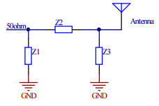
A basic manual tuner consists of either the Pi network mentioned above, which is a pair of variable shunt capacitors separated by a variable or selectable series inductor, or more commonly a T network, in which the capacitors are in series with the output path and are separated by an inductor which is a shunt to ground. As in the Pi network tuners, all three components are adjustable in some way. Modern automatic tuners use banks of caps and coils which are switched in by small relays, but they accomplish the same task in the end, which is matching the antenna impedance to the 50 ohm output of the transmitter. In spite of the near total dominance of auto-tuned radios on the market, the present day offering of external antenna tuners, both manual and automatic, is vast, with a staggering number of choices.
So why, if practically all radios sold in the recent past have a built-in automatic tuner, are external tuners so popular? To answer that fully, let us take a look at what an antenna tuner actually does and what it does not do. One thing that it does not do, despite the popular name, is tune the antenna. An antenna is normally tuned by changing its length. This sets the antenna’s resonant frequency. Every antenna has an impedance which consists of a resistive component (R), and a reactive component (X). By definition, the antenna’s resonant frequency is the frequency at which the reactance X is zero ohms. This can be, but is most likely not, the frequency at which the antenna will have a 1:1 VSWR. The reason for this is that a 1:1 VSWR will only exist if the R is 50 ohms, and most antennas are not 50 ohms. For example, a dipole in free space is about 72 ohms, and a quarter wave vertical over a proper ground is about half that, or 36 ohms.
Both of these antennas can be cut to resonance (X=0), and will still show a mismatch of about 1.4 to 1. What an “antenna tuner” does do, and do very well, is cancel reactance. An antenna which is not resonant at the desired frequency of operation will likely have a lot of reactance that needs to be countered, and a good external matching network will have a far greater matching range than the small auto tuners that are built into a modern HF radio. Most internal tuners will only match about a maximum of a 3:1 VSWR, but a good external tuner can handle ten times that, and that is one big reason why external antenna tuners have remained popular.
Another big reason for the popularity of external tuners is power handling capacity. If you own a high powered amplifier, the tuner in your radio will only match the radio to the amplifier’s input circuit. It will be of no value in matching the antenna once the amplifier is switched into the circuit. A large, high power antenna tuner can handle these duties for the QRO operator who needs more than just the 100 watt output of the radio. I have two full legal limit antenna tuners in my shack, and I use them both. They keep my kilowatt amplifier happy under a variety of antenna loads, including antennas which have been de-tuned by a buildup of ice. In several contests during ice storms, I have been able to keep on operating when others without antenna tuners have had to shut down. This can be a major competitive advantage.
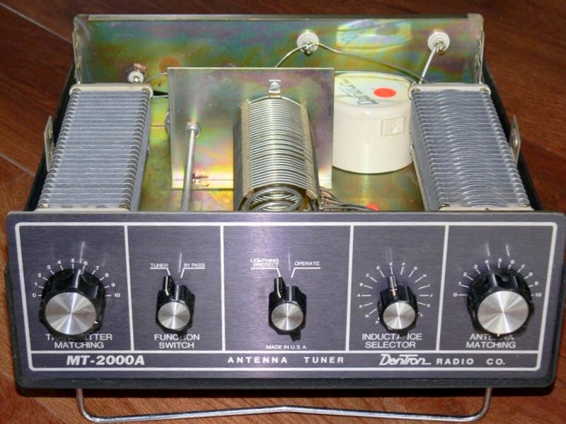
Even antennas which are properly tuned for the band of desired operation can benefit from a good external tuner when their VSWR bandwidth does not cover the entire band. On the lower bands of 80 and 160 meters, this is a significant issue since it is nearly impossible to build an efficient antenna which covers the entire band down there. My compact 160m vertical has a usable bandwidth of about 40 kHz, but by using my big DenTron tuner, I can easily double that. Operating a tuner on 160 will easily test its limits, and is the most likely
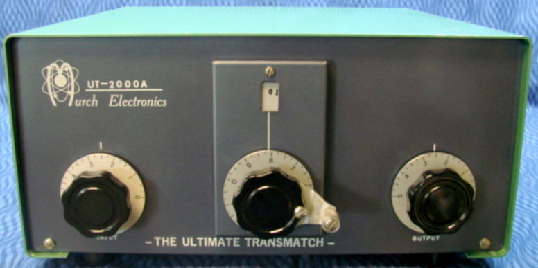
As far as which antenna tuner to buy, get the best one that you can afford. An old Johnson Matchbox, if you can find one, offers a fully balanced output if you are into Doublet antennas fed with ladder line. Many good older tuners like the Murch and DenTron units can be found at hamfests at a good price, but if you prefer to buy new, the Palstar units are built well and are in current production. Ameritron/MFJ is often a good value, but I usually suggest buying any MFJ product from a good dealer like HRO or DX Engineering rather than ordering from MFJ directly, to avoid any potential customer service problems.
band where a tuner will fail. The DenTron MT-2000A has never missed a beat, and I only use it on 160, at power levels up to a kilowatt. It is big, heavy, and bulletproof.
Generally, bigger is better when it comes to antenna tuners. When VSWR is high, the voltages developed in the tuning circuit can rise to surprisingly high levels. The only practical way to build big variable capacitors and inductors that can handle these voltages without arcing over is to increase the separation between the plates or coil turns, which in turn makes them very large. Physical size of these components is a good indicator of their ability to withstand the high voltages of a severe mismatch. Both of my tuners, the DenTron, and a somewhat smaller Drake MN-2000, have variable components of a large size. Neither has ever arced over on me, in spite of my best efforts to coerce them to. Very small antenna tuners are best reserved for QRP operation, as even a 100 watt signal can generate quite high voltages into a VSWR mismatch.
Another good practice which you should always adhere to is to keep the power levels down while adjusting the antenna tuner. Then, after you get a good match, you can crank it up and see how things are. If you try tuning a badly mismatched antenna at high power, you are likely to get all kinds of electrical fireworks in your tuner, amplifier, or both. This will be a mistake to regret, so it is best to avoid it altogether. You can actually do your initial tuning without even transmitting, just by adjusting for an increased noise level in the receiver. This will get you close. Then start with no more than about 30 or 40 watts until you have as close to a 1:1 VSWR as you can get. Once tuned, you can increase the power with some level of confidence that things are not going to arc and flash. The auto-tuners in most modern radios will reduce transmit power to about 10 watts or so when tuning, but for manual tuning you may need a bit more than this to get a good reading on your VSWR meter. Just use caution before applying full power.
|
|
In summary, I fully endorse the inclusion of a good, high power antenna tuner (or two) into every HF ham shack, even if you are only using resonant antennas. There will be times when having a tuner available will be well worth the expense, even if you don't use it all the time. I hope that all of you HF beginners out there will consider this important piece of equipment into your station budget for the reasons which I mentioned as well as others which I may not have. 73 and good DX to all!

|
Antennas In The Attic By Gary Mirkin, WA3SVW |
Antennas In The Attic. Sounds like the title of a Stephen King novel. No, it’s just the necessity of living in an H.O.A. (Home Owners Association) community. The rule is, “No Outside Visible Antennas” (sans for certain allowable satellite dishes.) What are we amateur radio operators to do, if we want decent performance regarding transmission, and reception, of our coveted electromagnetic environment? Some of us install (in the middle of the night?) stealth antennas that mimic ordinary outside objects, like flag poles, or fence posts. They still have to be “weather proofed”, and maintained, to stay healthy, not to mention hiding, and maintaining, the feed lines that connect our equipment to the aforementioned entities. Not my favorite project, as a senior. To my way of thinking, if you are fortunate enough to have the room, and access, is to install antennas in an attic space. My situation affords me the opportunity to do just that. Living in a rancher, that is almost 70 feet, in length, and with pull down stairs in the main hallway, of the house, leading to an attic space of almost the same length, with enough height, at it’s peak (over 6 feet), to walk upright.
With the help of a long time colleague, and friend, Rich P. (WA3IWT) we installed a long wire antenna (around 60 feet in total length), fed by a Icom AH-4 Auto Tuner, connected to my Icom IC-7000. We initially connected the wire as a dipole, and it served me well on the HF bands (160 through 6 meters) for several years. About a year ago, I started having trouble with the “Dipole” on the lower frequencies (160 & 80 meters), and decided to add a “backup” HF rig to the shack, with the addition of an Icom IC-7300 SDR rig. After trouble shooting the “malfunctioning” dipole, for open circuit, or “shorts” (found none), decided to re-think the configuration of the AH-4 so that one side goes to “Ground” (as it was designed), and the other goes to a Single Long Wire (instead of the two halves of the “dipole”). This solved most of the lower operating frequency problems. Added a second AH-4, with the same “Long Wire” configuration for the IC-7300. Ran a couple of longer single wire (as opposed to dipole) lengths, and added a coax switch, in the closet for the 7300 (the 7000 connects to just one wire. See Figure 1.
Since the IC-7000 also operates on 2m & 70cm (on a separate, connector), had to address the installation of an appropriate antenna. I chose the Diamond X50A Dual Band. It’s 5.6 feet in length, and can handle up to 200 Watts of power. More than enough for the 7000, and the linear amplifier I plan to add soon. Figures 2 & 3 show the antenna installed in the attic, next to the Solar conduit, running behind it, and a full view of the antenna in a QSL add, respectively.
Moving on to the IC-7300 setup. The 7300 is an HF (160 - 6 meter) radio, that has only one output connector. Since one wire length does not properly load on all bands, the three wire configuration, for the 7300 allows for switching to slightly different length wires to accommodate all the available HF bands the 7300 has to offer. I have to jump up from my operating position, to switch the coax, in the closet, however it’s not necessary very often, so no big deal. A comprehensive functional diagram appears at the end of this composition that shows how, and where all wires & antennas are switched.
Figure 4 shows some of the “long” wire runs in the attic. There are a total of four. One for the 7000, and three (through the coax switch, that uses just the center conductor contacts) for the 7300.
The wires are fed through the closet ceiling, to the attic, then along one side, then through a couple of 90 degree turns, and along the other side, to the far end of the attic. See Figures 5, 6, 7, 8, & 9.
Coverage for the third radio, is a Radio Shack Ham Discone Antenna. This ingenious piece of technology is only 44 inches, total length. It’s specifications state that it receives 25 - 1300 MHz (1.3 GHz), and loads up well, with low SWR and transmits effectively on 50, 144, 220, 440, 900, and 1296 MHz. It is the ideal attic antenna for my AnyTone D578UV III Pro Tri-Band (2m, 70cm, 1.25m) DMR/Analog rig, as well as, my SDR (Software Defined Radio) receiver (SDRplay), that tunes, and detects, any type radio signal, from 1 kHz, to 2000 MHz (2 GHz). Since this versatile antenna is shared by the AnyTone & the SDR receiver, I had to add a coax switch, so I could choose which radio “gets” the antenna. Figure 10 shows the switch installed on my station operating position.
The other antennas in the attic are “left over” spares I used when I had separate rigs for 2m, and 1.25m (220 MHz). They are mag mounts. One is “mounted” to metal ductwork, and the other is mounted to an old broiler pan, both acting as “ground planes” for the antennas. See Figures 11, 12, & 13.
Figures 12 & 13 show the 2m mag mount showing it’s operational frequency, and to what radio it was attached
The following, Figure 14, is a comprehensive functional diagram of the radios, SWR/Power Meters, and antenna switches of my “radio station”.
Hope the piece wasn’t too long, I tried to cover all the aspects of my attic installation effectively. The last image (Figure 15) is a shot of my station operating “Desk”, with most of the equipment “fired up”. I know it’s not the best, in the world, however, it’s very functional, for me, and, to my way of thinking, operates as efficiently as possible.
Thanks, to Mary, KD2PLH, for giving me the idea and encouragement to produce an article on my attic antennas.
How To PROPERLY Install A PL-259 Connector
By Tony Starr, K3TS
A common disparaging comment among the techno-snobs of ham radio is, "He can't even put on a PL-259". Well guess what? LOTS of people can't put on a PL-259! It seems to be one of ham radio's great mysteries, which has been made even more confusing by those who profess to have come up with a "better way". A case in point is the "K3LR Method". I like Tim Duffy, and he is a great contest operator, but I have to tell you, if you have shield braid sticking out the back of your connector (or anywhere on your connector) you have an improperly installed connector! A properly installed PL-259 should protect that shield braid from exposure to the elements and keep a good connection for years to come.
The very first thing that you must do, in order to get a properly installed PL-259, is to start with a good connector. The gold standard is the Amphenol 83-1SP. The only problem with those is that they are priced like the gold standard! And all of those shiny nickel plated connectors with the phenolic insulation, or worse, polystyrene, from Radio Shack and other stores of that ilk, all had two things in common: They did not take solder worth a darn, and the insulation was not able to handle the heat of the soldering operation. The connectors I will be using for this instructional article are from DX Engineering, and have a silver plated body and sleeve, with Teflon dielectric insulation. These connectors represent good quality at a decent price. Another good source of really good connectors at a decent price is our friend Joel at RF Connection in Maryland. Between these two sources are where I get all of my PL-259 connectors.
The coaxial cable that I use most often is RG-213, from either DX Engineering or HRO. This is the full size coax that is about the size of RG-8, or about 3/8 inch in diameter. The PL-259 is made for this size coax. If you wish to use smaller coax like RG-8x, or RG-58, you will need to use an appropriate adapter. When properly installed on the full size coax, the connector should not turn, slip, or pull out from the jacket of the cable. The end of the cable and the connector should be as one. Take the connector body in your hand and look into the large hole in the back. You will see some coarse threads in there, the ones that the RG-58 type adapters screw into. Those threads are designed to screw onto the PVC or PE jacket of RG-213 size cable. This makes a mechanically secure connection, and helps to keep out moisture and other contaminants.
Notice I said "helps to". A PL-259, unlike a Type N or even a BNC connector, does not contain any seals or gaskets, and is NOT watertight. You should never submerge a PL-259 connector, unless it has been "potted" in some kind of rubber or similar sealant. A properly installed PL-259 will shed water, and keep most rain and other moisture out if simply wrapped in a good electrical tape like Scotch 33 or 88. I have had many PL-259 connectors out in the weather, some for many years, and have never had a failure. If you follow these instructions to the letter, and practice a bit, you should have similar success.
Start with one end of the cable, and using a sharp utility knife, cut off the outer jacket back to at least 1½ inches from the end. Be careful not to knick the shield braid. then cut the shield braid back, until only about half an inch is left showing. Trim any "hairs" that could cause a short. Now cut the dielectric back until only about 1/8 inch of it is showing. Remove it by twisting it clockwise, which will tighten and improve the "lay" of the center conductor. A stranded conductor that is splayed out to where it is wider on the end is said to be "birdcaged". A birdcaged center conductor will not fit easily through the center pin of a PL-259. There is not a lot of extra clearance.
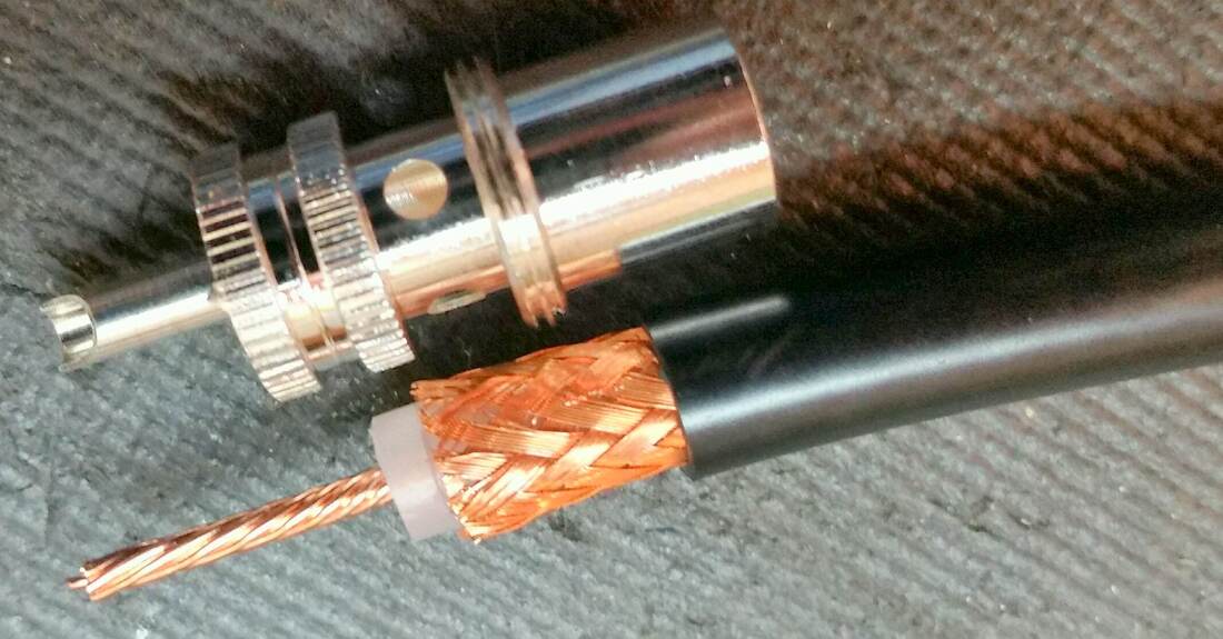
Figure 1
Take a look at Figure 1 above with the connector next to the prepared cable end. Note the relationship of the length of the prepared portion of the cable end to the connector itself. If you did prep the cable properly, little or no trimming should be needed. Before you start attaching the connector body to the cable, you must first take the outer sleeve and slide it on to the cable, or you will be cutting off your newly installed connector and tossing it into the trash. Since it is nearly impossible to de-solder one of these connectors, consider them to be non-reusable. Slide the sleeve far up the cable end enough to get it out of your way. Make sure the threads are facing the end of the cable!
Now take the connector and gently slide it over the prepared cable end. Be careful not to disturb the lay of the shield braid. When the connector body reaches the cable jacket, grip it firmly and twist it clockwise until the threads start to bite into the jacket. Keep turning and watch the four holes to make sure the shield is not twisting. Cable with a PVC jacket is much easier to screw the connector onto than cable with a polyethylene jacket. In either case, you may need to use a pair of pliers if you lose your grip on the connector. Try not to damage the connector with the pliers. Keep turning the connector until it "bottoms out". If this happens before the center conductor is extended beyond the end of the center pin, or before the shield braid is visible in the four holes, you may need to unscrew the connector and adjust things by trimming back the dielectric insulation a bit. Ultimately, before you start soldering, you want the connector to look like Figure 2 below. If the center conductor is sticking out too far, trim it now, flush with the end of the pin. Do not solder it and then trim it. This can fracture the solder connection and cause intermittent later, like after your antenna is up in the air. Not good.
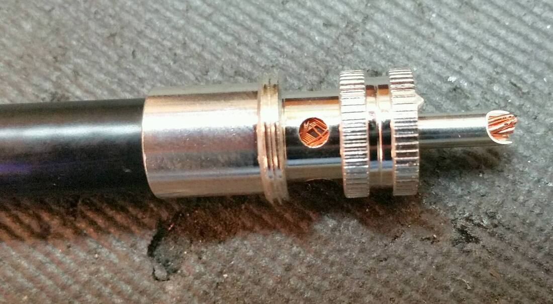
Figure 2
In order to solder this connector, you will need a soldering iron with adequate heat. The classic Weller soldering gun is certainly up to the task, even outdoors. On the bench, I use a temperature controlled pencil iron with a chisel tip of about 1/8 inch, set to at least 800 degrees. Adding a little rosin paste or liquid flux helps a lot, and should be considered a necessary step, even though you may be able to get along without it. I usually start with the center pin while the iron is still heating up because it does not need near as much heat as the shield holes do. Make sure the solder flows back into the pin. This is important. You don't want the only connection to be out on the end of the pin. When you start the shield holes, you may want to put some heat on the connector body and hold it for a while before applying the solder. Getting the body nice and hot will help the solder flow. Keep the iron against the knurled shoulder and away from the threads. If you get solder in those threads now, you will be cursing later!
When soldering the shield holes, you want to flow solder down into, but also up over the top of the holes. The holes should be sealed by the solder. You don't want an open hole for moisture to wick down into and corrode the shield. This solder operation is a little tricky and requires a bit of practice. Don't be afraid to go back and reflow the connection. Again, a bit of rosin flux really helps with this. Be sure to get all four holes sealed. This may require twisting the cable a bit in order to get to the far holes, and will require some way to hold it while you solder. I like to use a drill press vise with two small blocks of wood in it. I have various "electronic assembly vises", but the drill press vice is my go to for this.
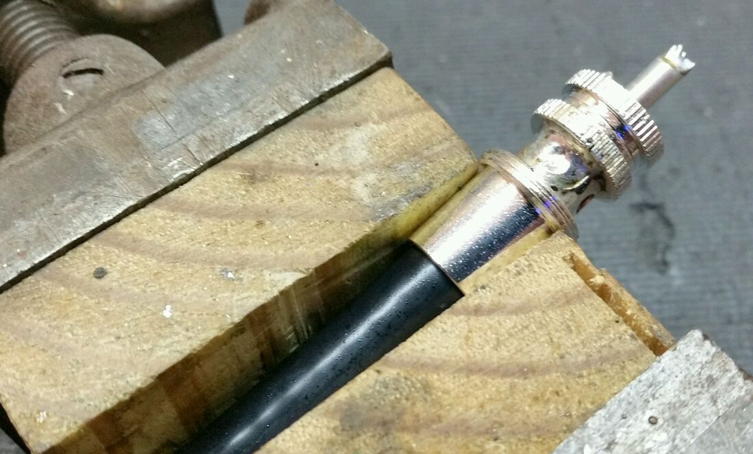
Figure 3
When you are finished soldering, clean the excess flux with a small acid brush and some 99% isopropyl alcohol, if you can find it. If not, 91% will do, but avoid the 70% "rubbing alcohol" as it may contain mineral oil. Besides, when was the last time you rubbed anything with alcohol? Just avoid that stuff! When you are done, the connector should be clean, bright and relatively weather resistant (see Figure 3 above). It should also be able to handle legal limit power. It is important that if you plan to install your own connectors, that you learn to do it properly. This is a common failure point that is easy to avoid. I have been out on Field Day and had connectors (not mine!) come off in my hand, because someone just grabbed a junk cable off the pile in the garage and threw it in the car. Why not avoid having "junk cables" in the first place? If you do it right, every cable will be a good reliable and trouble free cable. 73!
When you are finished soldering, clean the excess flux with a small acid brush and some 99% isopropyl alcohol, if you can find it. If not, 91% will do, but avoid the 70% "rubbing alcohol" as it may contain mineral oil. Besides, when was the last time you rubbed anything with alcohol? Just avoid that stuff! When you are done, the connector should be clean, bright and relatively weather resistant (see Figure 3 above). It should also be able to handle legal limit power. It is important that if you plan to install your own connectors, that you learn to do it properly. This is a common failure point that is easy to avoid. I have been out on Field Day and had connectors (not mine!) come off in my hand, because someone just grabbed a junk cable off the pile in the garage and threw it in the car. Why not avoid having "junk cables" in the first place? If you do it right, every cable will be a good reliable and trouble free cable. 73!
Congratulations on getting your first HF Radio! Now What?
By Jim Wright, N2GXJ
Thank you Santa! And congratulations! You’ve just got your first HF radio, and no matter what your license class is, you’re anxious to attach some kind of antenna to it, at least to hear what’s happening on the “ham bands”, and to maybe push that TX button up on your authorized portion of 10 meters for the first time to see if there’s anyone out there that can hear you!
But the antenna choices are bewildering! Where to start? Vertical, horizontal, so many choices! It’s “analysis paralysis”, so much to learn, so much advise, so many technical details, all so confusing.
I just want to do something, but I don’t want to do the wrong thing, what should I do? – Help!
Well, the great news is that you’re not alone. We all went through this, and the amazing lesson we learn is that you don’t have to be perfect, that it is OK to experiment, that it doesn’t have to cost a lot of money, and there are members of our club who are willing to help, if asked. Let’s step back for a moment, take a deep breath, and see what our options are.
Before you buy that “fancy” antenna, take some advice from the ARRL, and read this article http://www.arrl.org/building-simple-antennas. You’re going to encounter manufacturer claims that are, well, how to say this politely, designed to sell you their product, sometimes with wild claims. This is something that the ARRL, and us, your fellow Hams, would like to caution you about. For example, you generally won’t see claims of antenna gain in advertisements in QST magazine, because they have a strict policy that requires the manufacturer to prove it before they will publish it.
What I’m suggesting is maybe trying something simple first, while you shop around, and visit and talk with other hams for a while, to see what works best for them, and what doesn’t, before spending big money on something like an outdoor antenna system that you’re not likely to know that much about yet anyway.
So, now that I have a radio, but I don’t have an antenna yet, what would you recommend I do?
There are two suggestions, and they’re both simple.
First: As a member of the GCARC, you can be given the access and security alarm codes for our clubhouse trailer, and you can try out your new radio with both wire and beam antenna systems that we have set up out there! Also, you can get in-person help from a fellow ham on how to set up and operate that new radio. Starting in January, each month, on the first Saturday after our Wednesday general membership meeting, we’ll be having “Tech Saturdays” mornings out at the clubhouse. You can read more about this on our website on the "Tech Saturdays" page. There should be people there who can help you figure out “how does my radio work”, and help you get it on the air. So that’s my first suggestion. Make it easy on yourself. Bring your radio out for a "Tech Saturdays" morning, and with some help from other club members, see how it works with the different antennas available to try out at the clubhouse. Then after that, you can borrow the clubhouse setup whenever you want until you have something set up at home that you’d like to try and use.
Second: If you’ve tried the first suggestion, and now want to also be able to use your radio at home, you have two basic choices for your antenna: you can buy something, or build something. This being ham radio, I’d actually suggest building your first antenna, rather than buying one. But you’re welcome to buy or build as you desire. That’s part of the joy of ham radio!
So, from here on out, this article is just a recommendation for how I would suggest you would get started with your own home antenna. Others may, and probably will, have other opinions. That’s OK. I recognize there are many ways to accomplish the same goal, and this is just one of them. I’m not looking to be “flamed” by those who have different suggestions, or who might do it differently. I am just describing what worked for me, and am putting this out there for your consideration.
The recommended antenna is a really simple, inexpensive, and very forgiving design made from cut lengths of insulated wire attached in the center to a thing called a balun (which I’ll explain later). They call this antenna a multi-band or fan dipole. You don’t have to be perfect when putting it up, which makes it great for a starter antenna.
We’ll install this fan dipole up in the attic, so it is both protected from the weather, and won’t be able to be seen by prying neighbors. And we’ll build it using simple insulated wire, rather than tubing, so you might be able to save some cost by using materials that you or other club members might just have laying around. Your FCC license allows you to experiment with wire antennas for Ham radio like this, so why not have a little fun?
This antenna, is going to be in the attic you say? Yes. As described in the ARRL article http://www.arrl.org/indoor-antennas, if you have some sort of attic in your home, apartment or condo, you’re in luck. Attics are great locations for indoor antennas. They’re protected from the wind and weather, and from the prying eyes of neighbors. Let’s get something up there and try it!
When it comes to what to use to connect your radio to the antenna, don’t sweat it too much. This is HF radio, not UHF/VHF that we’re talking about. If you use a balun at the antenna as I suggest (explained later), you won’t need to use ladder line, making it very simple, and it will work just fine, to just use coax cable for the connection. Don’t worry about the precise length of coax – just buy or borrow a length long enough to get from your radio to the attic, with spare (that you can coil up in the corner somewhere).
If your radio has a built-in antenna tuner, and many new ones do, you’ll just connect the coax to the connector on the back of your radio. If it doesn’t, then connect it to the external antenna tuner you have separately attached to your HF radio. The other end goes up into the attic to connect to the balun in the center of the dipole antenna, as described next.
So what do I need to build this fan dipole?
1. A coax cable with male connectors each end, one end to attach to radio (or external tuner), and other end to attach to the bottom of the balun that will be at the center of our antenna. You run this from your radio up to the balun in the center of your attic. They typically come with connectors pre-installed, which makes it easier. The connector type should match what you need to connect to the back of your radio (or your external tuner, if one is not built into your radio), and to the balun described next.
2. A 1:1 current balun, that the antenna wire is attached to on the sides, and the coax cable connector screws into on the bottom. You hang the balun high in the center of your attic from the underside of the roof. The balun does triple duty for us as 1) a center point to attach each half of the wire antenna to, 2) a center point to attach a coax cable to, and 3) as a balanced-to-unbalanced transformer match between the wire antenna and the coax that also helps choke unwanted RF from running down the outside of the coax back into your shack. I bought one from Ham Radio Outlet in Delaware that was made by a company called RadioWavz that has threaded posts on the sides to make it easy to attach the wires to. Other choices are available.
3. One or more pairs of equal length 14 gauge insulated and stranded (not solid) wire, cut to specific lengths. You can find such at Lowes in the electrical section. I say stranded, not solid, because it is easier to work with. To make the equal length pair, you cut one piece to the full length specified, and then cut it in half, attaching each equal length half of the cut to opposite sides of the balun in the middle. My favorite web site for referencing wire antenna lengths is http://www.chem.hawaii.edu/uham/antennas.html. To make it easy, and to allow for a tiny bit of inevitable droop when trying to make them straight and level in the attic, you can follow the directions below, as a start, for your three wire antenna lengths. The wires are slightly longer than necessary on purpose, to accommodate the droop, but also to facilitate tuning by an expert by wrap-back length shortening, rather than adding, should you so desire to do so (you shouldn’t have to, but it’s still an option).
4. Some kite string, or clothes line, or other rope to tie things off up in the attic. Being in the attic, you have the advantage of not having to worry about the wind and weather; e.g. your antenna and supports are not going to get wet so you can ignore the extra steps you’d have to take to make this antenna and its connections and supports weather-proof for hanging outdoors.
When you’re done, it might look like this:
But the antenna choices are bewildering! Where to start? Vertical, horizontal, so many choices! It’s “analysis paralysis”, so much to learn, so much advise, so many technical details, all so confusing.
I just want to do something, but I don’t want to do the wrong thing, what should I do? – Help!
Well, the great news is that you’re not alone. We all went through this, and the amazing lesson we learn is that you don’t have to be perfect, that it is OK to experiment, that it doesn’t have to cost a lot of money, and there are members of our club who are willing to help, if asked. Let’s step back for a moment, take a deep breath, and see what our options are.
Before you buy that “fancy” antenna, take some advice from the ARRL, and read this article http://www.arrl.org/building-simple-antennas. You’re going to encounter manufacturer claims that are, well, how to say this politely, designed to sell you their product, sometimes with wild claims. This is something that the ARRL, and us, your fellow Hams, would like to caution you about. For example, you generally won’t see claims of antenna gain in advertisements in QST magazine, because they have a strict policy that requires the manufacturer to prove it before they will publish it.
What I’m suggesting is maybe trying something simple first, while you shop around, and visit and talk with other hams for a while, to see what works best for them, and what doesn’t, before spending big money on something like an outdoor antenna system that you’re not likely to know that much about yet anyway.
So, now that I have a radio, but I don’t have an antenna yet, what would you recommend I do?
There are two suggestions, and they’re both simple.
First: As a member of the GCARC, you can be given the access and security alarm codes for our clubhouse trailer, and you can try out your new radio with both wire and beam antenna systems that we have set up out there! Also, you can get in-person help from a fellow ham on how to set up and operate that new radio. Starting in January, each month, on the first Saturday after our Wednesday general membership meeting, we’ll be having “Tech Saturdays” mornings out at the clubhouse. You can read more about this on our website on the "Tech Saturdays" page. There should be people there who can help you figure out “how does my radio work”, and help you get it on the air. So that’s my first suggestion. Make it easy on yourself. Bring your radio out for a "Tech Saturdays" morning, and with some help from other club members, see how it works with the different antennas available to try out at the clubhouse. Then after that, you can borrow the clubhouse setup whenever you want until you have something set up at home that you’d like to try and use.
Second: If you’ve tried the first suggestion, and now want to also be able to use your radio at home, you have two basic choices for your antenna: you can buy something, or build something. This being ham radio, I’d actually suggest building your first antenna, rather than buying one. But you’re welcome to buy or build as you desire. That’s part of the joy of ham radio!
So, from here on out, this article is just a recommendation for how I would suggest you would get started with your own home antenna. Others may, and probably will, have other opinions. That’s OK. I recognize there are many ways to accomplish the same goal, and this is just one of them. I’m not looking to be “flamed” by those who have different suggestions, or who might do it differently. I am just describing what worked for me, and am putting this out there for your consideration.
The recommended antenna is a really simple, inexpensive, and very forgiving design made from cut lengths of insulated wire attached in the center to a thing called a balun (which I’ll explain later). They call this antenna a multi-band or fan dipole. You don’t have to be perfect when putting it up, which makes it great for a starter antenna.
We’ll install this fan dipole up in the attic, so it is both protected from the weather, and won’t be able to be seen by prying neighbors. And we’ll build it using simple insulated wire, rather than tubing, so you might be able to save some cost by using materials that you or other club members might just have laying around. Your FCC license allows you to experiment with wire antennas for Ham radio like this, so why not have a little fun?
This antenna, is going to be in the attic you say? Yes. As described in the ARRL article http://www.arrl.org/indoor-antennas, if you have some sort of attic in your home, apartment or condo, you’re in luck. Attics are great locations for indoor antennas. They’re protected from the wind and weather, and from the prying eyes of neighbors. Let’s get something up there and try it!
When it comes to what to use to connect your radio to the antenna, don’t sweat it too much. This is HF radio, not UHF/VHF that we’re talking about. If you use a balun at the antenna as I suggest (explained later), you won’t need to use ladder line, making it very simple, and it will work just fine, to just use coax cable for the connection. Don’t worry about the precise length of coax – just buy or borrow a length long enough to get from your radio to the attic, with spare (that you can coil up in the corner somewhere).
If your radio has a built-in antenna tuner, and many new ones do, you’ll just connect the coax to the connector on the back of your radio. If it doesn’t, then connect it to the external antenna tuner you have separately attached to your HF radio. The other end goes up into the attic to connect to the balun in the center of the dipole antenna, as described next.
So what do I need to build this fan dipole?
1. A coax cable with male connectors each end, one end to attach to radio (or external tuner), and other end to attach to the bottom of the balun that will be at the center of our antenna. You run this from your radio up to the balun in the center of your attic. They typically come with connectors pre-installed, which makes it easier. The connector type should match what you need to connect to the back of your radio (or your external tuner, if one is not built into your radio), and to the balun described next.
2. A 1:1 current balun, that the antenna wire is attached to on the sides, and the coax cable connector screws into on the bottom. You hang the balun high in the center of your attic from the underside of the roof. The balun does triple duty for us as 1) a center point to attach each half of the wire antenna to, 2) a center point to attach a coax cable to, and 3) as a balanced-to-unbalanced transformer match between the wire antenna and the coax that also helps choke unwanted RF from running down the outside of the coax back into your shack. I bought one from Ham Radio Outlet in Delaware that was made by a company called RadioWavz that has threaded posts on the sides to make it easy to attach the wires to. Other choices are available.
3. One or more pairs of equal length 14 gauge insulated and stranded (not solid) wire, cut to specific lengths. You can find such at Lowes in the electrical section. I say stranded, not solid, because it is easier to work with. To make the equal length pair, you cut one piece to the full length specified, and then cut it in half, attaching each equal length half of the cut to opposite sides of the balun in the middle. My favorite web site for referencing wire antenna lengths is http://www.chem.hawaii.edu/uham/antennas.html. To make it easy, and to allow for a tiny bit of inevitable droop when trying to make them straight and level in the attic, you can follow the directions below, as a start, for your three wire antenna lengths. The wires are slightly longer than necessary on purpose, to accommodate the droop, but also to facilitate tuning by an expert by wrap-back length shortening, rather than adding, should you so desire to do so (you shouldn’t have to, but it’s still an option).
- For 40 Meters, that also works on 15 Meters and on 6 Meters, you don’t have to be that exact. Cut one piece approximately 67 feet long, and cut in middle to make two equal 33 feet 6 inch halves to attach to the center balun. If you just put up this one dipole length, and none of the others, this one should let you talk with stations for several hundred miles up and down the East Coast fairly well during the day, and even better in the late afternoons and early evenings.
- For 20 Meters, cut one piece 34 feet long, and cut in middle to make two 17 foot long halves to attach to the center balun. If you’re putting up just one dipole in the attic, this might be the one to put up. Whereas the higher frequencies usually give out after dark, there are usually stations on this band at all hours of the day and most of the night, particularly on 14.070 MHz which is the frequency commonly used for PSK digital communications (one of my favorites).
- For 10 Meters, be a little more precise, and cut one piece 16 feet 10 inches, and cut in middle to make two 8 feet 5 inch long halves to attach to the center balun. If you’re just putting up this dipole, this one will let you have morning Europe contacts and afternoon West Coast contacts – but only temperamentally. Temperamentally because it’s up to somewhat unpredictable solar conditions for when this band is “open”, and when it is not. It’s kind of like fishing, you never know what you’ll catch unless you try on this band. Your attic dipole is high above ground, relative to a 10M wavelength, so when the band is open, you should be able to make some long distance contacts on this band.
4. Some kite string, or clothes line, or other rope to tie things off up in the attic. Being in the attic, you have the advantage of not having to worry about the wind and weather; e.g. your antenna and supports are not going to get wet so you can ignore the extra steps you’d have to take to make this antenna and its connections and supports weather-proof for hanging outdoors.
When you’re done, it might look like this:
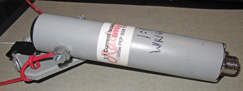
1:1 Current Balun
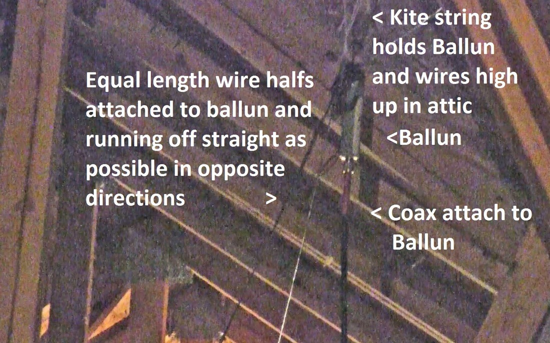
Attic Dipole
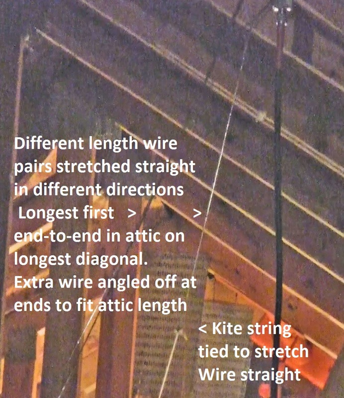
Attic Dipole String
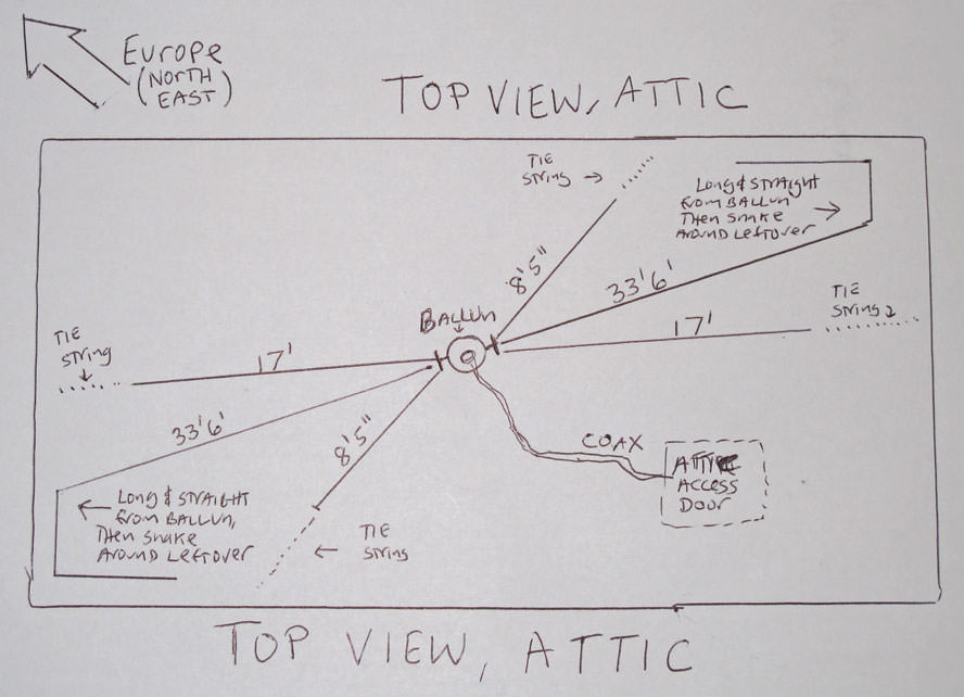
Attic Dipole - Top View
A YouTube video showing WD0AKX constructing such an antenna can be seen here: https://www.youtube.com/watch?v=8KHzsKYsZL0. You get the idea. He put his outside. We’ll put ours in the attic. And because we put ours in the attic, we don’t have to use those spacers between the wires that he built. Like he shows early in the video, you can run the wires off in different directions, instead of using spacers, which is really easy to do in the attic. So that’s what we’ll do.
Just put the balun up near the roof in the center of your attic and run the longest wires straight as far as you can in opposite directions from each other, then angle them around to make it all fit up there. The shorter pairs of wires, run those as far as you can in a straight line in opposite directions, again with the balun in the middle, but to different tie down points at a slightly different angle than the other wire pairs you put up.
Use kite string, or rope to tie to the end of the wire (can make a small knot at the end of the wire to attach the kite string to) and stretch out and attach to a convenient roof support in that direction in your attic. For the short antenna (the 10M antenna), if you can, you might want to stretch it broadside to the direction of Europe, as shown in the picture. From where we are in NJ, when the band is open, this will improve the strength of received signals from both Europe and South America, though any direction will do. For now, it’s just important to get something up there, and get on the air! You can always experiment later.
Also note that in the video, he added a wire for 6M, but says in the video he didn’t need it (because the 40M dipole already can be used with that band and an antenna tuner). To make things simpler for our antenna, we won’t include it. I don’t think you’ll miss it. That band isn’t used much, and having more wire pairs makes it harder to attach the wire bundle to each side of the balun.
Once you have it built, and installed, you can borrow an expert’s “SWR meter” to measure how perfect it is on the different bands, but as shown in the video, with your antenna tuner, it probably won’t matter much. After that, you’re on the air, and then off to experimenting with other antenna types no doubt, like back yard verticals, and various forms of wire or yagi beams.
So that’s it! Once again, congratulations on your new radio! Hope to catch you on the air soon!
Jim Wright, N2GXJ