Combination Capacitor Leakage & ESR Tester
|
Back in February 2022, I decided to design and build a multi-function capacitor tester (Figure 1) for use in my shop. The reason for this project was because I could not find a decent tester at a reasonable price that would make the specific tests in which I was interested. What I wanted was a unit that could test a capacitor for leakage, and then test the same capacitor for its equivalent series resistance (ESR). |
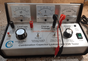
Figure 1 : Combination Capacitor Tester
|
Capacitor leakage occurs when a capacitor begins to behave more like a resistor than it does a capacitor, in that it begins passing DC rather than blocking it. The more leakage a capacitor exhibits, the more DC current will pass through that capacitor.
ESR is one of the failure modes of a capacitor, specifically that in which a capacitor has begun to dissipate energy and thus begin to heat up. Most capacitors will have some specific ESR that is permitted by the manufacturer, and that limit will generally be specified on the capacitor datasheet. ESR represents the AC resistance of a capacitor that causes that capacitor to dissipate energy. Generally speaking, the higher the nominal value of a capacitor, the lower the ESR specification will be. In a perfect or “ideal” capacitor, the ESR will be zero. In the real world, however, components are not ideal, and every component has some variance from the specifications of an ideal component of that type and value.
Being an AC resistance, ESR is measured at some given frequency, often on the order of 120Hz for linear power supply capacitors, 100kHz for switchmode power supply capacitors, and 1kHz for audio capacitors. For simplicity of my design, I had to decide on a single test frequency to be used that would enable at least a representative measurement to be made. I settled on 100Hz for my ESR section’s oscillator because that is a value often specified by capacitor manufacturers for ESR specification testing.
The tester is comprised of two printed circuit boards (Figure 2), a leakage test section and the ESR test section. Each board has its own power supply, as the power requirements for the two boards are considerably different. The leakage section uses a transformer with a 230VAC center-tapped secondary, and outputs voltages up to five hundred volts DC. The ESR section is operated from a five-volt DC supply. Each section is fused independently, and there is also a master fuse for the entire unit. Thus, the rear panel (Figure 3) carries three fuse holders as well as the power inlet.
The rear panel also has markings regarding the power source and general safety information and warnings, while the top panel (Figure 4) is labeled with the operating instructions. The front panel, a dual-angle panel, carries three meters as well as all of the operating controls. In addition, the front panel has leakage (volt) meter output jacks and the device-under-test (DUT) binding posts.
All of the labeling of the unit panels was accomplished via water-slide decals printed on my color laser printer and installed in the same manner in which we used to apply decals to model airplanes when we were kids. The decal is soaked in warm water for a few seconds, and then is slid off its backer sheet and into place on the panel to which it is being applied. The excess water is blotted out from behind the decal, and then the decal is allowed to dry. Once dry, it is protected by two light coats of clear spray enamel. The funny thing is that this project enclosure started out with a white painted upper half. The problem was that I cut the openings for the meters in the wrong places and ruined the piece. Thus, I had to have a new panel cut and bent by a local metal supplier, so I ended up with the natural finish rather than the white surfaces that were originally intended to be there.
The individual schematics of the two sections (Figures 5 and 6) incorporate the necessary controls and meters, and also have some oddities. For example, when originally designed, the ESR section PCB was intended to have a fuse on the PCB. During construction however, I decided to move that fuse to the rear panel, so as to make the unit a no-open design as regards fuse replacement. Both PCB’s have the power transformers for the individual stages directly mounted to the PCB.
This saved some real estate in the enclosure and enabled me to reduce the size of the enclosure required, which in turn provided for a more aesthetically-pleasing tester design. Figure 8 shows the overall wiring diagram for the tester.
The three panel meters include a leakage current meter (0-500µA), a charge voltage (test voltage) meter (0-500V), and the ESR meter (0-50µA). The ESR meter has a custom meter face (Figure 7) that was created and installed into the meter, so that the meter is calibrated in ohms of ESR, from zero ohms to over ten ohms.
The front panel has an indicator LED that illuminates to show that the power is good on the ESR board. The front panel controls are as follows :
The leakage current meter output jacks are intended for connection to an accurate voltmeter. Due to the internal resistances in the circuit, an indicated reading of one volt on the voltmeter equates to one milliampere of leakage current. Because the onboard leakage meter is calibrated only to 500µA, the external meter connection allows accurate reading of leakages in excess of that limitation, as well as more accurate readings of leakages that fall within the onboard meter range. The front panel DUT binding posts are polarized as is necessary for the proper testing of polarized capacitors such as tantalum or electrolytic capacitors.
All of the front panel controls and wiring are accessible via the removal of four flat-head machine screws from the underside of the tester, and then by tilting the upper half of the enclosure open (Figure 9). Full access is then available to every part of the assembly, with the wire harnesses securely bundled for safety and security of the wiring. The PCB’s are mounted to the floor of the enclosure; all other parts are mounted to the enclosure upper half. The enclosure itself sits on four rubber cushions that are installed into ¼” holes drilled in the floor of the enclosure.
Testing of a capacitor involves first discharging the capacitor, then connecting it to the DUT binding posts. Set the tester power switch to its ON position. Set the function switch to Leakage and set the leakage test activity switch to Test. Then, adjust the charge voltage adjust control clockwise until the charge voltage meter reads the rated working voltage of the capacitor. Read the leakage in µA directly off the leakage current meter. Return the charge voltage adjust control to its fully-counter-clockwise position, and then switch the leakage test activity switch to the Discharge position, which will cause the charge in the capacitor to be bled off. After about thirty seconds, switch the function switch to ESR. Press and hold the zero short switch and adjust the ESR meter zero adjust control to align the ESR meter pointer with the zero mark on the meter scale. Release the zero short switch and read the ESR in ohms directly from the ESR meter. Place the function switch into its OFF position to conclude the test.
An acceptable capacitor will have no or very minimal leakage and will exhibit extremely low ESR when tested in this manner. Electrolytic capacitors, especially those with high capacitance values, will take a longer time period for the leakage test, and may require raising the charge voltage in stages to avoid running the leakage current meter violently off-scale. This is because all electrolytic capacitors will exhibit heavy leakage until they are charged to a sufficient level for proper testing. The higher the capacitance value, the longer the test will take. Eventually, the meter will stabilize at some point. Ideally, the leakage will be at or below the datasheet maximum leakage limit when the charge voltage is at the capacitor’s working voltage. Consistently high leakage, or the inability to reach the rated working voltage is indicative of excessive leakage and the capacitor should be scrapped.
Some datasheet leakage values are expressed as various arcane statements like…
What does all of that mean? Let’s take them one at a time…
What happens is that each manufacturer provides the leakage formulation that has been chosen for the particular capacitor at hand. From any one given manufacturer, the leakage value formula may change from one capacitor series to another. In fact, the second a third examples above are for two different capacitor families from the same manufacturer. Sometimes, a specified time is stated, and often, a given ambient or test temperature is also stated. Some manufacturers do not specify a maximum leakage value on their datasheets. In those cases, a judgement call must be made. As can be seen from the above examples, however, is that in no case was the leakage unreasonably high. All of the examples cited above were for electrolytic capacitors, as they are often the most difficult to test accurately. Low leakage is always to be desired.
I have tested some film capacitors that exhibited no leakage that could be seen on the meter in my tester. I have also tested some electrolytics that went off the leakage scale as soon as any charge voltage was applied, and I could never get the charge voltage to register more than about twenty or twenty-five volts, because it leaked down as quickly as it was applied. In a case like that, the capacitor is, for all intents and purposes, shorted and readily passing DC. That same capacitor, however, may well test fairly well as regards ESR, which (don’t forget) is an AC test. It is for this reason that both tests are made, and that either test can condemn a capacitor to the scrap bin.
Sometimes, a manufacturer will give a range of specifications for leakage and ESR for the capacitors covered by a datasheet, with individual values being shown for each capacitor listed. In these cases, there will sometimes even be multiple leakage specifications under different test standards, temperatures, or time periods. Read the datasheet carefully when determining the values to use as your guide. Consider the datasheet excerpt at Figure 10. This datasheet provides individual leakage current values, two for each capacitor, and an ESR value for each capacitor listed.
Take for example the 470µF 6.3V capacitor in the excerpt. Its one-minute leakage current would be 22µA while its five-minute leakage current would be 11µA. The ESR value shown for this capacitor is 0.85Ω when tested at 100Hz. Why does the leakage current go down as the time period is extended? Because the capacitor has had longer to charge and so should be fully charged, and the dielectric should be fully formed. The initial leakage will be higher than the later leakage. This is a clear-cut example of what I meant when I said earlier that testing electrolytics can take some time, and that their leakage values will go down with time if the capacitor is viable. If the leakage value does not decrease, the capacitor is scrap.
I have been using this tester for the full year-and-a-half since I built it, to great success. It has proven to be a sturdy and reliable tester, even with its limitations. The limitations of which I speak are the maximum charge voltage of 500 volts, and the maximum onboard leakage current metering of 500µA. The leakage current limitation is easily overcome with an external voltmeter. The charge voltage limit, however, is a hard limit.
On the other hand, if a test must be made of a capacitor that has a working voltage in excess of 500 volts, a pretty safe conclusion can be drawn by the capacitor’s performance up to and at that 500-volt limit. If the leakage is high at lower voltages, it is a safe bet that it will also be high at the full working voltage. However, if the leakage is low at the 500-volt limit, it may increase as the working voltage goes up. What this leaves us with is a way to condemn those capacitors with high leakage, but a remaining question for those with low leakage evident at the 500-volt tester limit. Nothing is perfect. I had to draw the line somewhere in designing this unit, and I went with a charge voltage limit that I felt was reasonable at the time. Truth be told, I have only had one instance of not being able to accurately test a high-voltage capacitor. It happens rarely enough that I can live with it.
I am pleased with the appearance and performance of this unit. It looks like it was factory-made, and it performs like a much more expensive device. Best of all, it does exactly the tests that I needed done, and it does them reliably for the overwhelming majority of the capacitors that I have had reason to test.
ESR is one of the failure modes of a capacitor, specifically that in which a capacitor has begun to dissipate energy and thus begin to heat up. Most capacitors will have some specific ESR that is permitted by the manufacturer, and that limit will generally be specified on the capacitor datasheet. ESR represents the AC resistance of a capacitor that causes that capacitor to dissipate energy. Generally speaking, the higher the nominal value of a capacitor, the lower the ESR specification will be. In a perfect or “ideal” capacitor, the ESR will be zero. In the real world, however, components are not ideal, and every component has some variance from the specifications of an ideal component of that type and value.
Being an AC resistance, ESR is measured at some given frequency, often on the order of 120Hz for linear power supply capacitors, 100kHz for switchmode power supply capacitors, and 1kHz for audio capacitors. For simplicity of my design, I had to decide on a single test frequency to be used that would enable at least a representative measurement to be made. I settled on 100Hz for my ESR section’s oscillator because that is a value often specified by capacitor manufacturers for ESR specification testing.
The tester is comprised of two printed circuit boards (Figure 2), a leakage test section and the ESR test section. Each board has its own power supply, as the power requirements for the two boards are considerably different. The leakage section uses a transformer with a 230VAC center-tapped secondary, and outputs voltages up to five hundred volts DC. The ESR section is operated from a five-volt DC supply. Each section is fused independently, and there is also a master fuse for the entire unit. Thus, the rear panel (Figure 3) carries three fuse holders as well as the power inlet.
The rear panel also has markings regarding the power source and general safety information and warnings, while the top panel (Figure 4) is labeled with the operating instructions. The front panel, a dual-angle panel, carries three meters as well as all of the operating controls. In addition, the front panel has leakage (volt) meter output jacks and the device-under-test (DUT) binding posts.
All of the labeling of the unit panels was accomplished via water-slide decals printed on my color laser printer and installed in the same manner in which we used to apply decals to model airplanes when we were kids. The decal is soaked in warm water for a few seconds, and then is slid off its backer sheet and into place on the panel to which it is being applied. The excess water is blotted out from behind the decal, and then the decal is allowed to dry. Once dry, it is protected by two light coats of clear spray enamel. The funny thing is that this project enclosure started out with a white painted upper half. The problem was that I cut the openings for the meters in the wrong places and ruined the piece. Thus, I had to have a new panel cut and bent by a local metal supplier, so I ended up with the natural finish rather than the white surfaces that were originally intended to be there.
The individual schematics of the two sections (Figures 5 and 6) incorporate the necessary controls and meters, and also have some oddities. For example, when originally designed, the ESR section PCB was intended to have a fuse on the PCB. During construction however, I decided to move that fuse to the rear panel, so as to make the unit a no-open design as regards fuse replacement. Both PCB’s have the power transformers for the individual stages directly mounted to the PCB.
This saved some real estate in the enclosure and enabled me to reduce the size of the enclosure required, which in turn provided for a more aesthetically-pleasing tester design. Figure 8 shows the overall wiring diagram for the tester.
The three panel meters include a leakage current meter (0-500µA), a charge voltage (test voltage) meter (0-500V), and the ESR meter (0-50µA). The ESR meter has a custom meter face (Figure 7) that was created and installed into the meter, so that the meter is calibrated in ohms of ESR, from zero ohms to over ten ohms.
The front panel has an indicator LED that illuminates to show that the power is good on the ESR board. The front panel controls are as follows :
- Function switch - select between Leakage, ESR, and OFF;
- Leakage test activity switch - select between Test and Discharge;
- Charge voltage adjust - used to set the test voltage for the leakage test;
- ESR meter zero adjust - used to set the ESR meter to zero ohms;
- Zero short switch - used to set ESR meter circuit to its zero-adjust function; and
- Power switch - used to turn the tester on and off.
The leakage current meter output jacks are intended for connection to an accurate voltmeter. Due to the internal resistances in the circuit, an indicated reading of one volt on the voltmeter equates to one milliampere of leakage current. Because the onboard leakage meter is calibrated only to 500µA, the external meter connection allows accurate reading of leakages in excess of that limitation, as well as more accurate readings of leakages that fall within the onboard meter range. The front panel DUT binding posts are polarized as is necessary for the proper testing of polarized capacitors such as tantalum or electrolytic capacitors.
All of the front panel controls and wiring are accessible via the removal of four flat-head machine screws from the underside of the tester, and then by tilting the upper half of the enclosure open (Figure 9). Full access is then available to every part of the assembly, with the wire harnesses securely bundled for safety and security of the wiring. The PCB’s are mounted to the floor of the enclosure; all other parts are mounted to the enclosure upper half. The enclosure itself sits on four rubber cushions that are installed into ¼” holes drilled in the floor of the enclosure.
Testing of a capacitor involves first discharging the capacitor, then connecting it to the DUT binding posts. Set the tester power switch to its ON position. Set the function switch to Leakage and set the leakage test activity switch to Test. Then, adjust the charge voltage adjust control clockwise until the charge voltage meter reads the rated working voltage of the capacitor. Read the leakage in µA directly off the leakage current meter. Return the charge voltage adjust control to its fully-counter-clockwise position, and then switch the leakage test activity switch to the Discharge position, which will cause the charge in the capacitor to be bled off. After about thirty seconds, switch the function switch to ESR. Press and hold the zero short switch and adjust the ESR meter zero adjust control to align the ESR meter pointer with the zero mark on the meter scale. Release the zero short switch and read the ESR in ohms directly from the ESR meter. Place the function switch into its OFF position to conclude the test.
An acceptable capacitor will have no or very minimal leakage and will exhibit extremely low ESR when tested in this manner. Electrolytic capacitors, especially those with high capacitance values, will take a longer time period for the leakage test, and may require raising the charge voltage in stages to avoid running the leakage current meter violently off-scale. This is because all electrolytic capacitors will exhibit heavy leakage until they are charged to a sufficient level for proper testing. The higher the capacitance value, the longer the test will take. Eventually, the meter will stabilize at some point. Ideally, the leakage will be at or below the datasheet maximum leakage limit when the charge voltage is at the capacitor’s working voltage. Consistently high leakage, or the inability to reach the rated working voltage is indicative of excessive leakage and the capacitor should be scrapped.
Some datasheet leakage values are expressed as various arcane statements like…
- “After 1 minute's (for case size 10 × 12.5 or smaller) or 2 minutes' (for case size 10 × 16 or larger) application of rated voltage at 20°C, leakage current is not more than 0.002CV or 0.2 (μA) whichever is greater”;
- “I = 0.003 CV + 4.0 (µA); C = rated capacitance (µF), V = rated voltage (VDC). Voltage applied for 5 minutes at +20°C”; or
- “I = 0.005 CV (μA); C = rated capacitance (µF), V = rated voltage (VDC)”.
What does all of that mean? Let’s take them one at a time…
- Depending upon the capacitor case size, the maximum leakage current will be either 0.2µA or 0.002 x the working voltage (V) x the capacitance (C) in µF… after the working voltage has been applied for the specified time period for that particular case size. Suppose we had a 470µF capacitor rated at 25V in a 10mm x 12.5mm case. We would apply the test voltage of 25 volts for a period of one minute, at which time the maximum leakage should be 0.002 x 470 x 25, or 23.5µA, as the multiplied value is greater than the 2µA minimum, and the specification stipulated “whichever is greater”.
- In this case, the formula changes to 0.003 x C x V, with the voltage applied for five minutes. Using the same capacitor values, we would get a maximum leakage value of (0.003 x 470 x 25) + 4µA, or 35.25µA + 4µA, for a total of 39.25µA.
- In the third example, we are given no time and no minimum or additive value. It is a straight arithmetic equation of 0.005 x C x V. Using the same capacitor again, we would now have 0.005 x 470 x 25, or 58.75µA as the maximum leakage value permitted.
What happens is that each manufacturer provides the leakage formulation that has been chosen for the particular capacitor at hand. From any one given manufacturer, the leakage value formula may change from one capacitor series to another. In fact, the second a third examples above are for two different capacitor families from the same manufacturer. Sometimes, a specified time is stated, and often, a given ambient or test temperature is also stated. Some manufacturers do not specify a maximum leakage value on their datasheets. In those cases, a judgement call must be made. As can be seen from the above examples, however, is that in no case was the leakage unreasonably high. All of the examples cited above were for electrolytic capacitors, as they are often the most difficult to test accurately. Low leakage is always to be desired.
I have tested some film capacitors that exhibited no leakage that could be seen on the meter in my tester. I have also tested some electrolytics that went off the leakage scale as soon as any charge voltage was applied, and I could never get the charge voltage to register more than about twenty or twenty-five volts, because it leaked down as quickly as it was applied. In a case like that, the capacitor is, for all intents and purposes, shorted and readily passing DC. That same capacitor, however, may well test fairly well as regards ESR, which (don’t forget) is an AC test. It is for this reason that both tests are made, and that either test can condemn a capacitor to the scrap bin.
Sometimes, a manufacturer will give a range of specifications for leakage and ESR for the capacitors covered by a datasheet, with individual values being shown for each capacitor listed. In these cases, there will sometimes even be multiple leakage specifications under different test standards, temperatures, or time periods. Read the datasheet carefully when determining the values to use as your guide. Consider the datasheet excerpt at Figure 10. This datasheet provides individual leakage current values, two for each capacitor, and an ESR value for each capacitor listed.
Take for example the 470µF 6.3V capacitor in the excerpt. Its one-minute leakage current would be 22µA while its five-minute leakage current would be 11µA. The ESR value shown for this capacitor is 0.85Ω when tested at 100Hz. Why does the leakage current go down as the time period is extended? Because the capacitor has had longer to charge and so should be fully charged, and the dielectric should be fully formed. The initial leakage will be higher than the later leakage. This is a clear-cut example of what I meant when I said earlier that testing electrolytics can take some time, and that their leakage values will go down with time if the capacitor is viable. If the leakage value does not decrease, the capacitor is scrap.
I have been using this tester for the full year-and-a-half since I built it, to great success. It has proven to be a sturdy and reliable tester, even with its limitations. The limitations of which I speak are the maximum charge voltage of 500 volts, and the maximum onboard leakage current metering of 500µA. The leakage current limitation is easily overcome with an external voltmeter. The charge voltage limit, however, is a hard limit.
On the other hand, if a test must be made of a capacitor that has a working voltage in excess of 500 volts, a pretty safe conclusion can be drawn by the capacitor’s performance up to and at that 500-volt limit. If the leakage is high at lower voltages, it is a safe bet that it will also be high at the full working voltage. However, if the leakage is low at the 500-volt limit, it may increase as the working voltage goes up. What this leaves us with is a way to condemn those capacitors with high leakage, but a remaining question for those with low leakage evident at the 500-volt tester limit. Nothing is perfect. I had to draw the line somewhere in designing this unit, and I went with a charge voltage limit that I felt was reasonable at the time. Truth be told, I have only had one instance of not being able to accurately test a high-voltage capacitor. It happens rarely enough that I can live with it.
I am pleased with the appearance and performance of this unit. It looks like it was factory-made, and it performs like a much more expensive device. Best of all, it does exactly the tests that I needed done, and it does them reliably for the overwhelming majority of the capacitors that I have had reason to test.