Coaxial Cable Tester

Figure 1 : CMS CCT-01 Coaxial Cable Tester
As a technician who assembles a multitude of coaxial cables, I find it tiresome to test these cables with an ohmmeter, not because of the effort that it takes, but because it is rather clumsy to do so easily with only the two hands that we are given at birth. As a result, I set out to design and build a device that would test coaxial cables of each of the four basic types used in radio, those types being the SMA, the BNC, the UHF, and the N type cables.
I wanted my tester (Figure 1) to effectively check for continuity of both the center conductor and the shield braid, and also to look for shorts between the center and shield circuits. My other design requirements were self-containment, portability, compact size, and the ability to test cables with mixed connector types, e.g., with an SMA connector on one end and a BNC connector on the opposite end.
I laid out a circuit that uses three transistors, six resistors, and three LED’s. The complete parts list is provided in Table 1. The transistors used happen to be two BC547 NPN types and one BC557 PNP type, though any general-purpose switching or small-signal transistors will suffice. The LED’s are of the T1-3/4 or 5mm size, with two of them being green and the third being red. I chose the 5mm LED’s for better visibility. If enclosure top-surface real estate is an issue, 3mm LED’s can be used instead.
The enclosure that I selected for this project is one that I had on hand, which turns out to be a 1554-series unit from Hammond Industries, in light grey. Quite frankly, it is slightly oversized for the strict needs of this project, but it happens to meet the most important criterion for the enclosure. It is critical that the cable jacks are mounted to a non-conductive surface, making a plastic enclosure almost a requirement so as to meet that need without having to jump through hoops to get there.
A schematic diagram of the unit is shown in Figure 2. The cable connectors used in this build are all of the bulkhead-mount style, where the jack is secured to the panel via a hex nut on the external threads of the connector body. A solder lug is secured under the hex nut, tight against the panel. Within each set of four connectors, the connector bodies are wired together at their solder lugs and then again at their center terminals. However, the two sets must be isolated from each other. If the connectors were to be installed to a metal or otherwise conductive panel, the outer continuity test for the shield braid would be obviated.

The two switches, SW1 and SW2, which are mounted to the front panel, are used respectively for mode selection and for test activation. The MODE switch has a center OFF position, in which all battery current is interrupted. When placed in its SHORTS position, current is available to the PNP transistor and the circuit path that is used to detect short-circuits between the center conductor and the shield braid of the cable under test. When the MODE switch is placed in its CONTINUITY position, the cable under test is checked for a complete circuit path through its center conductor, while simultaneously being checked for shield braid integrity. The testing is performed by pressing and holding the TEST switch with the MODE switch in the desired test position.
Note that the front panel is marked “SHORT TEST THIS SIDE” beneath the cable jacks on the left side of the panel (Figure 3). To completely test a cable, begin by connecting one end of the cable to one of the connector jacks on the left side of the device, to a connector in the group that is marked with the “SHORT TEST…” label. It does not matter which end of the cable is connected, nor which jack in that group is used. If necessary to make the connection, an appropriate gender adapter can be inserted between the cable and the jack. Once one end of the cable is properly connected, move the MODE switch to its SHORTS position, and then press and hold the TEST switch button. If the cable has any short circuit between the inner conductor and the shield braid, the red LED will illuminate. If the red LED does not illuminate during this test, it is time to move on to the continuity test.

Figure 3 : Front Panel Layout & Markings
The test results are always indicated by the LED’s on the front panel. Each LED is labeled as to its purpose, those purposes being inner continuity, outer continuity, and shorts. An intact cable, with no breaks in continuity, will illuminate both green LED’s when the cable is connected at both ends, the MODE switch is in its CONTINUITY position, and the TEST button is pressed. The label adjacent to each green LED will indicate the test condition that is reported by that LED.
This cable tester is powered by a single nine-volt snap-top alkaline battery, which should have quite an extensive service life. The maximum current draw, which occurs during the continuity test, is only about 25.33mA. Surprisingly, the current draw during the shorts test is 22.66mA. The current draw disparity is most likely due to the green LED’s being more efficient than is the red LED. A typical test will only last a matter of one or two seconds - just long enough to see that both LED’s are illuminated. Accidental discharge of the battery is prevented by the center-off functionality of the MODE switch.
The fact that this device incorporates all of the most common coaxial cable types used in Amateur Radio makes it the perfect addition to any ham’s shack. The total cost is under thirty dollars, and that amount can be reduced by eliminating any connector types that the user is certain will never be needed. Of course, the connectors, in the overall scheme of things, are not that expensive and I would prefer to see the continued versatility afforded by having all four connector types installed.
The sharp-eyed reader will notice, when looking at the interior view of the tester shown in Figure 4, that there is something odd about the N connectors used. Those observant souls are correct. The connectors used turned out not to be standard N-type panel-mount jacks, but instead are modified N-female x N-female bulkhead connectors. I had an abundance of these bulkhead connectors on hand, for which I seldom have a need. As a result, I decided to modify a pair of these connectors to make the jacks that I needed. A couple of minutes with a cut-off wheel in my Dremel® tool, and I had cut the bulkhead connectors down to a panel-mount jack configuration. The funny thing about this decision was the matter of cost differences involved. The bulkhead connectors used had a price tag of about $3.50 each, while the Amphenol 172185 N panel jacks come in at about $17.00 each from Mouser or Digikey. Of course, I also sourced a less expensive alternative vendor for those parts, so that I could bring them in at about four dollars each if needed.

Figure 4 : Interior View Of Cable Tester
It was mostly out of laziness that I delved into this project. However, it has turned out to be a viable tool and valuable addition to my workbench. While the physical layout of the front panel is purely a matter of taste, preference, and available space management, I ended up choosing a layout that has all of the “input” connectors, used for the shorts test, grouped on the left side of the front panel, while the connectors for the opposite end of the cable under test are arranged on the right-hand side (See Figure 5). Between the connector groups, the two switches and the three LED’s are arranged, with the MODE switch nearest the lower edge, and the TEST switch near the upper edge. The LED’s are arranged in a cluster in the center, with the red LED at the very center and the green LED’s on either side.
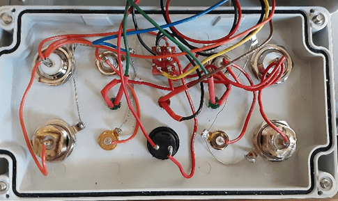
Figure 5 : Front Panel Wiring Close-Up View
Labels were printed with my Dymo Rhino 5200 label printer as black lettering on clear tape. The labels were then trimmed to fit in the available spaces. I added my logo decal to the front panel, and the job was done.
This device has gotten considerable use in the short while since I built it, as I now test every cable that I assemble, as well as any existing cables that I have not yet tested or that have been in long-term use.
Testing of cables in long-term use is a valid concept, especially when trying to track down a signal loss problem. In that case, however, I would go one step further and test the cable directly for its signal loss or attenuation value using a vector network analyzer. While this new tester can locate shorts and opens, it cannot really identify cable losses unless those losses are bad enough to appear as an open to the test circuit.
Through creative use of adapters and known good cables, this device can also be used to test the basic condition of cable adapters and other feed-through devices such as watt meters or SWR bridges. Remember, though, that all this device will tell you is whether or not the two through circuit paths are intact and if those two paths are crossed or shorted.
I will most likely build another of these units, so that I can donate it to the GCARC Test & Repair Bench, where it can get plenty of use. It would make a great addition to any ham’s bench.

Table 1 : Complete Parts List