|
HecKits FET Dip Meter |
Coil Chart
FET Dip Meter Build
By Chris Prioli. AD2CS
OK - it’s back into the build shop again, this time to gin up a FET Dip Meter from a kit. The kit, which includes all parts and components required for the build (including a pre-machined enclosure) comes from HecKits (www.heckits.com), a web store operated by the kit designer and ham Darrel Heckendorf WA7OIB. Darrel is quick to respond to e-mails and provides a phone number on his website. He operates from Cedar Park, Texas and ships via USPS Priority Mail. My order was prepped and shipped and a tracking number provided the same day that I placed the order, and my order required some customization - more on that later.
So… what exactly is a dip meter? Originally, it was called a “grid dip meter” and it was designed to indicate just that - a decrease or “dip” in the grid current of a vacuum tube when the meter was coupled to a resonant circuit. With the passing of the vacuum tube, the “grid” part got dropped from the name, and though the circuits are now solid-state, the operation is the same. Basically, a dip meter is a tunable oscillator with the coil that determines the oscillator frequency exposed so that it can easily be inductively coupled to another operating circuit. A dip meter typically includes an analog meter whose movement can be used to alert the user to the fact that a coupled circuit is in resonance, indicated by a noticeable drop or “dip” in the meter’s indication. While MFJ no longer offers its last dip meter, the MFJ-201, they do offer plug-in coil sets for use with certain other devices currently sold, allowing those units to be used as dip meters, so the concept is not a dead one.
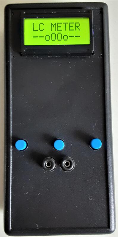
Rather than the frequency dial that many older dip meters used, the unit produced from this kit has an 8 x 2 LCD panel for the frequency read-out, and a small analog meter for the dip indicator. The unit is powered by a 9 volt alkaline battery. The overall size of the meter is 7.5” x 2.5” x 1.1”, including the #2 coil (which is the longest coil form) protruding from the top of the enclosure. The protruding coil is one of five coils normally provided with the meter kit, only one of which (coil #1) is pre-wound when the kit is shipped. The remaining four coils will need to be wound by the kit builder. Complete illustrated instructions are provided. The coils are wound on cylindrical pre-drilled forms, and then the magnet wire leads are soldered to three-pin DIN plugs, which then mate with a DIN socket at the meter enclosure’s top panel when the coil is in use. Once frequency ranges are established and the wire is in place properly on the forms, it is held there by clear heat-shrink tubing over the form.
As the kit is usually sold, it includes, as already mentioned, a total of five coils, providing overlapping frequency ranges as follows :
These coils give the dip meter continuous coverage for the ham bands from 160 meters through 10 meters. I say “as the kit is usually sold” because I did not buy the standard kit. Darrel gave me the option, at no additional cost, of upgrading my kit to a meter that would cover the 6-meter band as well, which necessitated the change of one resistor in the unit’s meter current voltage divider chain (from 2KΩ to 100Ω), the addition of another 10KΩ bias resistor in the Q4 base circuit, and a change to the last coil. This change to the last coil is accomplished by adding a sixth coil for the 6-meter version of the kit, this one having a total of 4 turns (1.5T + 2.5T) and providing a frequency range from 15.45 MHz to >60 MHz.
Remember that I said that the coils are wired to three-pin DIN plugs? Each of the coils has a tap at some fixed distance from its low end. In each case, the tap is accomplished by actually winding two separate coils on the form, with Pin 2 connecting to the high end of the first coil and the low end of the second coil. The wires are passed to the plug pins via the hollow core of the form, through holes drilled in the form for that purpose. In the case of coil #6, which uses half-turns, the half-turns are accomplished by simply bringing the magnet wires to the common pin (Pin 2) out through a drilled hole on the “back” side of the cylindrical form, or half-way around the form.
One point that I found a bit disconcerting is the fact that not all components are assigned component identifier values (R1, C5, D3, etc.), while others are assigned identifiers. In fact, the 1N4001 diode in the power supply circuit has no identifier, while the two varactor diodes in the tuning circuit do have them, but the 1N4148 diode at the gate of Q1 and the 1N270 germanium diode at the gate of Q2 again have no identifiers. It doesn’t make much sense to me, and my organized mind wants identifiers to be present throughout. Add to the fact that there are few component identifiers is the fact that there is also no PCB screen print at all. This means that the builder has to correlate the PCB image in the instructions, which has component outlines by value, with the myriad of holes in the PCB and hope that everything ends up where it belongs.
In my PCB design experience, unless I made the boards at home, there was no additional cost for an upper-surface screen print. The board in this kit looks professionally made, and there are some connection indicators etched into the board’s top surface (such as M+, M-, 9V, etc.), so a screen print should not have been out of the question. Due to the fact that there is a lot number etched on the board, I believe that the board was factory-made, in which case the missing screen print is egregious. Figures 1 shows the PCB as shipped in the kit.
One other small detail that I found to be an annoyance was that the zip-top poly bag containing the small parts was not properly sealed prior to packing and shipping, meaning that some of the small parts escaped the poly bag in transit and were loose in the carton. This allowed some to spill when the carton was opened. Fortunately, I found all of the pieces that spilled out. As a matter of fact, and probably due to the fact that some components were pre-installed, there was one extra 10kΩ resistor in the kit when all was said and done.
The enclosure arrives completely pre-machined with all necessary holes and openings already cut. In fact, the LCD panel and the meter are already fastened to the enclosure upper half. There is also a piece of sponge adhered to the enclosure upper half in the battery box area, obviously to help keep the battery from flopping around inside the enclosure - a nice touch.
The PCB also has some components already installed - most notably a pair of 10kΩ resistors that share a common hole in one location, one of which is installed on end, with one lead being connected through a tiny hole drilled through the board and into a trace on the foil side. In addition, there is an extended lead of the other 10kΩ resistor in a piece of tubing crossing over one trace on the PCB and soldered to another trace. These are obviously modifications to the original board. I was informed by the kit designer that these modifications were made to accommodate the 6-meter band capability.
The parts count is relatively low. The reason that the meter is called a “FET Dip Meter” is because the “working” heart of the unit is a pair of J310 N-channel depletion-type JFET’s. The “thinking” heart of the unit is a PIC16F628A microcontroller in a DIP-18 package. The µC ships pre-programmed. All components are through-hole devices, making it very builder-friendly. LCD contrast is controlled via a 5kΩ pot.
The build instructions are so complete that they spell out every step of the build, individual component by individual component. The kit includes a rudimentary nut driver for the tiny 2-56 hex nuts used to secure the various parts of this unit to the enclosure. It is perfectly adequate for its intended purpose.
Because the PCB is secured in the enclosure lower half when shipped, it is a good idea to re-install the hex nuts onto their studs when removing the PCB for assembly thereof. That way, the tiny nuts won’t get lost during PCB assembly. The meter can be worked in place without removal being necessary, but the LCD panel will need to be uninstalled so that the connector wires can be installed to it. Again, take care not to lose the retaining hex nuts.
Assembly was slow but mostly straightforward, starting as is my custom with the lowest-profile components first, and then working my way up to the taller components. The lack of a screen print made the job tedious. As such, the resistors were first, followed by the diodes, observing diode polarity on installation. This was done by aligning the marked or striped end (cathode) of the diode with the striped end of the diode outline on the PCB print in the instructions. After the diodes came the chokes. Next came the polarized capacitors, which must be installed with care towards observing their polarity. Some of the polarized caps are tantalum types which will usually have the positive side marked. Electrolytics, on the other hand, will usually have their negative sides marked. Take the time to ascertain which way each cap should be installed before inserting it into the PCB. After the polarized caps, I installed the ceramic chip and monolithic capacitors, and then the 10MHz crystal and the trimmer capacitor, making sure to seat both of these components fully flush against the PCB and orienting the trimmer cap with its flat side towards the crystal. See Figures 3, 4, and 5.
Next in line came the LM7805 5-volt voltage regulator IC, the 5kΩ trimmer potentiometer (used for LCD panel contrast adjustment) and the 18-pin IC socket for the µC. The voltage regulator and the IC socket are polarity-sensitive. When installing the voltage regulator, it is necessary to bend the leads at a 90° angle to the component body right at the component body, bending them downward, or away from the device markings. Insert the regulator with its tab towards the near edge of the PCB, ensuring that the IC sits flat on the PCB and that its tab does not extend past the edge of the PCB. The IC socket has a notch at one end. This notch must be aligned toward the “bottom” edge of the PCB, according to the instructions. There is no visual indicator of proper socket orientation, either on the PCB or on the PCB print in the instructions. Just orient it so that the notched end is towards the nearest edge of the PCB.
Now it was time to install the pin headers. There are three of these, a 2-pin for the meter connection, and a four-pin and a six-pin that are used for the LCD panel connections. The four-pin and six-pin headers are angled headers, and they get installed with the angled pins pointing towards the “bottom” of the PCB. In fact, the four-pin header’s pins will overlap the 18-pin IC socket when properly installed.
After the pin headers, the two 10kΩ 30-turn potentiometers were installed. These two pots are installed on spacer blocks which lift them up from the PCB. It is important to press the pots and spacers firmly against the PCB so that they cannot rock side-to-side after installation. Next, the knobs are installed to the pots. The knobs have a pop-off escutcheon on the outer end, which conceals an adjustment screw. To install the knob, remove the escutcheon and loosen the Phillips screw underneath. Slide the knob onto the potentiometer shaft, holding it slightly above the pot body, and tighten the screw to secure the knob to the shaft. Insert the escutcheon back into the knob and that job is done. See Figures 6 and 7.
Next up are the transistors and varactor diodes. The two J310 FET’s are installed according to their outlines in the PCB print in the instructions. Be careful to insert the FET leads into the proper holes in the PCB - there are four holes at each FET location. Go by the PCB print to see which holes are used. The 2N3904 and PN2222A transistors are straightforward, just be sure to install each one in its proper location, again orienting them in accordance with the PCB print. Finally, the two varactor diodes are installed, once again using the PCB print outlines for orientation guidance.
I installed the DIN socket and the power switch next, and then the battery snap connector. There is a pre-soldered wire loop near the battery snap wire connect points through which the wires should be passed to provide some strain relief for the battery wires. However, upon assembly, I did not think that the wire loop alone provided adequate strain relief for the battery leads. So, I used a resistor clip-off lead to form a wire bail around the leads and the loop, securing the battery leads to the wire loop. This completed the build of the PCB subassembly, so I carefully inspected the solder work for cold joints and for solder bridges, while also verifying that every pin or lead had been soldered. After a successful inspection, I installed the PCB into the enclosure lower half, just snugging the retaining hex nuts enough so that they would stay put. See Figures 8, 9, and 10.
Note that it can be very tricky to get the tiny 2-56 hex nuts started on their studs, especially when the studs are in close quarters among PCB components or in close proximity to the enclosure sides. A method that I have used quite successfully is to slide the nut onto the blade of my smallest jeweler’s screwdriver, then, holding the nut in place on the blade, place the tip of the screwdriver blade against the end of the stud. Let the nut slide down against the stud, and then give the nut a little bit of a spin, using the tip of another fine screwdriver to turn the nut. Once the nut has started on the stud threads, use the nut driver to secure the nut.
Wiring of off-board components was simple enough, with all wiring steps clearly delineated in the build instructions. The six-lead pre-wired plug and harness gets connected to pins 1 through 6 of the LCD panel, connecting the wires from the foil or “back” side of the LCD panel. The wire color and pin sequence is the familiar electronics color scheme - brown to pin 1, red to pin 2, orange to pin 3, yellow to pin 4, green to pin 5, and blue to pin 6. The four-lead pre-wired plug and harness is connected in the same manner to pins 11 through 14 of the LCD panel, again with the color scheme of brown to pin 11, red to pin 12, orange to pin 13, and yellow to pin 14. The wired LCD panel is shown in Figure 11. Ultimately, these two harnesses will be connected to the angled pin headers on the PCB with the brown wires to the left when the board is viewed with the DIN socket away from you.
The two-lead pre-wired plug and harness gets connected to the meter, with the red or pink wire going to the positive terminal and the black or grey wire going to the negative terminal. After soldering the leads in place, slide the heat-shrink tubes in place over the terminals and apply some heat to shrink them there. Then, gently bend the terminals downward to place them alongside the meter housing. Ultimately, this harness will be connected to the two-pin straight pin header with the black or grey lead closest to the bottom edge of the PCB when the board is held with the DIN socket away from you. The PCB is marked M+ and M- next to these two pins on the header. The completed top half of the unit is shown in Figure 12.
Once the basic build is complete, but before installing the µC to its socket, a check for the 5VDC operating voltage is called for. This is done by connecting the battery to its snap, flipping the power switch to its “ON” position, and measuring the voltage at various points on the PCB, always with respect to ground (the battery negative lead tie point). Locations that should measure +5VDC (nominal) are Pin 3 of the LM7805 voltage regulator, Pins 4 and 14 of the µC, and Pin 2 of the LCD panel. On the other hand, the meter + terminal should have the full 9VDC present, as should the 39kΩ resistor at the drain of Q2 and the 270Ω resistor at the drain of Q1.
Once the operating voltages check out, turn the power switch “OFF” and verify that the voltages - both 9VDC and 5VDC - are no longer present. If all is OK, it is now time to install the µC in its socket, taking care to align the notch or dot on the IC with the notched end of the IC socket. This orientation should lead to the dotted or notched end of the IC (the Pin 1 end) being towards the bottom of the unit.
After installing the µC into the IC socket, it is time to connect the two harnesses form the LCD panel to the angled pin headers on the PCB. As already mentioned, the harnesses will be connected with the brown wire towards the left on each plug when viewed with the DIN socket away from you. Then connect the meter harness to the two-pin header with the black or grey lead towards the bottom edge of the PCB, as already mentioned.
Turn the unit on and verify that the LCD panel is active. You may need to adjust the 5kΩ potentiometer to bring the LCD contrast into proper adjustment for viewing. If you cannot get the display to go active, power down and check carefully for solder bridges at the LCD panel wire connect points and on the main PCB, especially in the vicinity of the microcontroller IC.
A brief word is due here about coil changes. I strongly advise that the unit always be powered down to make a coil change. I don’t know that any actual harm will come from hot-swapping a coil, but why take the chance? It’s a simple flip of a slide switch to “OFF”, change the coil, and then slide the switch back to “ON”.
It only takes a second or so, and it could forestall damage to your dip meter. If the display is active, power down and insert the pre-wound coil #1 into the DIN socket, then move the power switch to its “ON” position. The unit should oscillate from around 1.30 MHz to 2.80 MHz, as indicated on the LCD panel. The 10kΩ 30-turn pot on the left side of the unit is the unit’s Calibration control. It should be adjusted to obtain a reading of about 2/3 of the frequency range, or about 2.305 MHz. It may take numerous turns of the calibration pot to get the calibration to that point, but once there, only minor adjustment will be needed when working with the higher frequencies. Observe the meter while moving your finger near the coil. Your finger may cause the meter to do its characteristic dip, but don’t be alarmed if it doesn’t.
If all works as it should, it is time to close up the case. Remove the coil from the DIN socket. Carefully arrange the wire leads to keep them clear of the meter housing. Allow the battery to hang free through the battery compartment door opening. Insert the end plate of the enclosure into its slot, making sure that the DIN socket is aligned with the hole in the plate. Then bring the two halves of the enclosure close to each other, aligning the end plate with its slot in the upper half of the enclosure, and while aligning the two pot knobs with their holes in the top half, bring the two halves together. Secure them to each other using the four black screws provided for this purpose. The basic meter is now complete, and it is time to begin winding the remaining four (or five) coils.
Winding the coils is simply a matter of following the illustrated guides presented in the instructions - one for each coil. The various coils use a couple of different wire gauges for their windings as follows :
As shipped, the wire is, for the most part, separated and tagged by the coil number for which it is intended to be used. The exception to this is a small spool of wire tagged for coils 2 and 3. Also, each coil form is identified with a numbered label again with the exception of coils 4 and 5, which use identical forms. The inconsistency in methodology was an affront to my ordered mind, but it was not insurmountable. I simply applied the supplied labels to each of the unlabeled coil forms. I suppose, if one were so inclined, that a similar label could be affixed to each coil form identifying the frequency range for which the coil is used. I chose instead to place that information on a chart affixed to the back of the enclosure.
As each coil was wound and the wire tails were brought out through the hollow core of the coil form, I cut each tail off at about one-half inch length. Each tail was then stripped of its enamel coating and tinned in preparation for soldering to the DIN plug pins. Stripping and tinning of most enameled magnet wire is most easily done by wetting the tip of your soldering iron with a fresh drop of solder, and then dragging the wire tail through that solder drop. The heat of the molten solder will burn away the enamel coating, which will be replaced by a coating of solder on the wire tail. While the enamel coating can also be mechanically removed by repeatedly pulling the wire through a folded piece of 400-grit sandpaper, I find the solder method to be quicker and cleaner.
Each coil is wound by starting the magnet wire through the low hole in the form and passing it through the coil form until your half-inch tail is achieved. Then, wind the requisite number of turns for the low coil, and pass the wire end through the mid-height hole in the coil form and down through the hollow core, cutting it off even with the first tail at one-half inch. Now, pass the end of the remaining wire through the mid-height hole in the coil form again, establishing a tail length of one-half inch as before. Wind the requisite number of turns for the high coil and pass the wire end through the high hole in the coil form, again leading it down through the hollow form core to match up with the other tails. Cut it off at the now familiar length of one-half inch. Figure 13 shows the wound coils before the leads were trimmed, stripped, and tinned. Strip and tin all four wire tails. Solder the wire from the low hole to pin 1 of the DIN plug. Twist the two wires from the mid-height hole together and solder them to pin 2 of the DIN plug. Solder the wire from the high hole to pin 3 of the DIN plug. Insert the provided form plug disc into the upper end of the form. DO NOT apply the heat shrink tube to the coil yet - this will be done later. Repeat the winding process for each of the remaining coil forms. Also, DO NOT snap the DIN plug into the lower end of the coil form yet. This will be done after coil calibration and wire securement has been accomplished.
Once all of the coils have been wound, they are one by one inserted into the DIN socket and their frequency ranges are established. The upper and lower frequencies are adjusted by changing the spread of the wires turns in the individual coils. When you have the correct positioning set, maintain the wire positions temporarily with some clear tape such as packing tape. After all of the coils have been fine-tuned, the clear heat shrink tubing is applied to the coil forms and is shrunk into place with the application of some heat. Then snap the DIN plug into the lower end of each coil form. The coils are now ready for use, as shown in Figure 14.
The astute reader will have noticed that I have not discussed the right-hand 10kΩ 30-turn potentiometer of the 4.5pF to 20pF trimmer capacitor yet. I have not forgotten them. The right-hand pot is the unit’s Frequency adjustment and is used to adjust the bias voltage on the varactor diodes, changing their capacitance and thus adjusting the frequency of the oscillator.
The trimmer capacitor is there as a hedge against an off-spec 10 MHz crystal in the PIC16F628A clock circuit. Although these crystals seldom vary from their specified frequency by more than 100 Hz or so, it is possible, so the trimmer cap is there to bring the clock frequency to exactly 10 MHz. Of course, adjustment of the trimmer requires the use of an accurate frequency counter. Fortunately, this is seldom an issue as it is not very critical to the operation of the overall unit. Figure 15 shows the working unit.
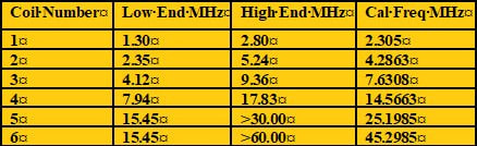
I said earlier that I affixed a label to the back of the unit listing the frequency ranges of the various coils. This chart also shows the calibration frequency for each coil - remember?? That 2/3 of the range point? It looks something like the Coil Chart at the top of the page.
In using the dip meter, I generally start with the Frequency control set to its approximate mid-point. Then, once I insert a coil, I adjust the Calibration control to the Cal Freq for the coil number in use. Next, I bring the unit into close parallel proximity to the circuit to be measured for resonant frequency. Now I adjust the Frequency control until I note the dip in the meter indication. The frequency shown on the LCD panel will be the resonant frequency of the circuit under test.
All things considered, this was an interesting build with its share of challenges. It was certainly doable, and it works as advertised. I would recommend this build for someone with moderate experience level - I would not advise that a beginner try this one. The inexperienced builder will likely become confused and frustrated in attempting this build. That said, the unit is of a relatively high finished quality. It could be improved upon by some front panel labels. I overcame the label issue by printing a self-adhesive label for the front panel, identifying the various controls and meters. Figures 16 and 17 show the labels that I affixed to the completed unit. This is something that the kit supplier might have done to really put this kit over the top.
By Chris Prioli. AD2CS
OK - it’s back into the build shop again, this time to gin up a FET Dip Meter from a kit. The kit, which includes all parts and components required for the build (including a pre-machined enclosure) comes from HecKits (www.heckits.com), a web store operated by the kit designer and ham Darrel Heckendorf WA7OIB. Darrel is quick to respond to e-mails and provides a phone number on his website. He operates from Cedar Park, Texas and ships via USPS Priority Mail. My order was prepped and shipped and a tracking number provided the same day that I placed the order, and my order required some customization - more on that later.
So… what exactly is a dip meter? Originally, it was called a “grid dip meter” and it was designed to indicate just that - a decrease or “dip” in the grid current of a vacuum tube when the meter was coupled to a resonant circuit. With the passing of the vacuum tube, the “grid” part got dropped from the name, and though the circuits are now solid-state, the operation is the same. Basically, a dip meter is a tunable oscillator with the coil that determines the oscillator frequency exposed so that it can easily be inductively coupled to another operating circuit. A dip meter typically includes an analog meter whose movement can be used to alert the user to the fact that a coupled circuit is in resonance, indicated by a noticeable drop or “dip” in the meter’s indication. While MFJ no longer offers its last dip meter, the MFJ-201, they do offer plug-in coil sets for use with certain other devices currently sold, allowing those units to be used as dip meters, so the concept is not a dead one.
Rather than the frequency dial that many older dip meters used, the unit produced from this kit has an 8 x 2 LCD panel for the frequency read-out, and a small analog meter for the dip indicator. The unit is powered by a 9 volt alkaline battery. The overall size of the meter is 7.5” x 2.5” x 1.1”, including the #2 coil (which is the longest coil form) protruding from the top of the enclosure. The protruding coil is one of five coils normally provided with the meter kit, only one of which (coil #1) is pre-wound when the kit is shipped. The remaining four coils will need to be wound by the kit builder. Complete illustrated instructions are provided. The coils are wound on cylindrical pre-drilled forms, and then the magnet wire leads are soldered to three-pin DIN plugs, which then mate with a DIN socket at the meter enclosure’s top panel when the coil is in use. Once frequency ranges are established and the wire is in place properly on the forms, it is held there by clear heat-shrink tubing over the form.
As the kit is usually sold, it includes, as already mentioned, a total of five coils, providing overlapping frequency ranges as follows :
- Coil #1 - 95 turns total (19T + 76T) - 1.30 MHz to 2.80 MHz
- Coil #2 - 62 turns total (12T + 50T) - 2.35 MHz to 5.24 MHz
- Coil #3 - 27 turns total (5T + 22T) - 4.32 MHz to 9.36 MHz
- Coil #4 - 13 turns total (2T + 11T) - 7.94 MHz to 17.83 MHz
- Coil #5 - 7 turns total (2T + 5T) - 15.45 MHz to >30MHz
These coils give the dip meter continuous coverage for the ham bands from 160 meters through 10 meters. I say “as the kit is usually sold” because I did not buy the standard kit. Darrel gave me the option, at no additional cost, of upgrading my kit to a meter that would cover the 6-meter band as well, which necessitated the change of one resistor in the unit’s meter current voltage divider chain (from 2KΩ to 100Ω), the addition of another 10KΩ bias resistor in the Q4 base circuit, and a change to the last coil. This change to the last coil is accomplished by adding a sixth coil for the 6-meter version of the kit, this one having a total of 4 turns (1.5T + 2.5T) and providing a frequency range from 15.45 MHz to >60 MHz.
Remember that I said that the coils are wired to three-pin DIN plugs? Each of the coils has a tap at some fixed distance from its low end. In each case, the tap is accomplished by actually winding two separate coils on the form, with Pin 2 connecting to the high end of the first coil and the low end of the second coil. The wires are passed to the plug pins via the hollow core of the form, through holes drilled in the form for that purpose. In the case of coil #6, which uses half-turns, the half-turns are accomplished by simply bringing the magnet wires to the common pin (Pin 2) out through a drilled hole on the “back” side of the cylindrical form, or half-way around the form.
One point that I found a bit disconcerting is the fact that not all components are assigned component identifier values (R1, C5, D3, etc.), while others are assigned identifiers. In fact, the 1N4001 diode in the power supply circuit has no identifier, while the two varactor diodes in the tuning circuit do have them, but the 1N4148 diode at the gate of Q1 and the 1N270 germanium diode at the gate of Q2 again have no identifiers. It doesn’t make much sense to me, and my organized mind wants identifiers to be present throughout. Add to the fact that there are few component identifiers is the fact that there is also no PCB screen print at all. This means that the builder has to correlate the PCB image in the instructions, which has component outlines by value, with the myriad of holes in the PCB and hope that everything ends up where it belongs.
In my PCB design experience, unless I made the boards at home, there was no additional cost for an upper-surface screen print. The board in this kit looks professionally made, and there are some connection indicators etched into the board’s top surface (such as M+, M-, 9V, etc.), so a screen print should not have been out of the question. Due to the fact that there is a lot number etched on the board, I believe that the board was factory-made, in which case the missing screen print is egregious. Figures 1 shows the PCB as shipped in the kit.
One other small detail that I found to be an annoyance was that the zip-top poly bag containing the small parts was not properly sealed prior to packing and shipping, meaning that some of the small parts escaped the poly bag in transit and were loose in the carton. This allowed some to spill when the carton was opened. Fortunately, I found all of the pieces that spilled out. As a matter of fact, and probably due to the fact that some components were pre-installed, there was one extra 10kΩ resistor in the kit when all was said and done.
The enclosure arrives completely pre-machined with all necessary holes and openings already cut. In fact, the LCD panel and the meter are already fastened to the enclosure upper half. There is also a piece of sponge adhered to the enclosure upper half in the battery box area, obviously to help keep the battery from flopping around inside the enclosure - a nice touch.
The PCB also has some components already installed - most notably a pair of 10kΩ resistors that share a common hole in one location, one of which is installed on end, with one lead being connected through a tiny hole drilled through the board and into a trace on the foil side. In addition, there is an extended lead of the other 10kΩ resistor in a piece of tubing crossing over one trace on the PCB and soldered to another trace. These are obviously modifications to the original board. I was informed by the kit designer that these modifications were made to accommodate the 6-meter band capability.
The parts count is relatively low. The reason that the meter is called a “FET Dip Meter” is because the “working” heart of the unit is a pair of J310 N-channel depletion-type JFET’s. The “thinking” heart of the unit is a PIC16F628A microcontroller in a DIP-18 package. The µC ships pre-programmed. All components are through-hole devices, making it very builder-friendly. LCD contrast is controlled via a 5kΩ pot.
The build instructions are so complete that they spell out every step of the build, individual component by individual component. The kit includes a rudimentary nut driver for the tiny 2-56 hex nuts used to secure the various parts of this unit to the enclosure. It is perfectly adequate for its intended purpose.
Because the PCB is secured in the enclosure lower half when shipped, it is a good idea to re-install the hex nuts onto their studs when removing the PCB for assembly thereof. That way, the tiny nuts won’t get lost during PCB assembly. The meter can be worked in place without removal being necessary, but the LCD panel will need to be uninstalled so that the connector wires can be installed to it. Again, take care not to lose the retaining hex nuts.
Assembly was slow but mostly straightforward, starting as is my custom with the lowest-profile components first, and then working my way up to the taller components. The lack of a screen print made the job tedious. As such, the resistors were first, followed by the diodes, observing diode polarity on installation. This was done by aligning the marked or striped end (cathode) of the diode with the striped end of the diode outline on the PCB print in the instructions. After the diodes came the chokes. Next came the polarized capacitors, which must be installed with care towards observing their polarity. Some of the polarized caps are tantalum types which will usually have the positive side marked. Electrolytics, on the other hand, will usually have their negative sides marked. Take the time to ascertain which way each cap should be installed before inserting it into the PCB. After the polarized caps, I installed the ceramic chip and monolithic capacitors, and then the 10MHz crystal and the trimmer capacitor, making sure to seat both of these components fully flush against the PCB and orienting the trimmer cap with its flat side towards the crystal. See Figures 3, 4, and 5.
Next in line came the LM7805 5-volt voltage regulator IC, the 5kΩ trimmer potentiometer (used for LCD panel contrast adjustment) and the 18-pin IC socket for the µC. The voltage regulator and the IC socket are polarity-sensitive. When installing the voltage regulator, it is necessary to bend the leads at a 90° angle to the component body right at the component body, bending them downward, or away from the device markings. Insert the regulator with its tab towards the near edge of the PCB, ensuring that the IC sits flat on the PCB and that its tab does not extend past the edge of the PCB. The IC socket has a notch at one end. This notch must be aligned toward the “bottom” edge of the PCB, according to the instructions. There is no visual indicator of proper socket orientation, either on the PCB or on the PCB print in the instructions. Just orient it so that the notched end is towards the nearest edge of the PCB.
Now it was time to install the pin headers. There are three of these, a 2-pin for the meter connection, and a four-pin and a six-pin that are used for the LCD panel connections. The four-pin and six-pin headers are angled headers, and they get installed with the angled pins pointing towards the “bottom” of the PCB. In fact, the four-pin header’s pins will overlap the 18-pin IC socket when properly installed.
After the pin headers, the two 10kΩ 30-turn potentiometers were installed. These two pots are installed on spacer blocks which lift them up from the PCB. It is important to press the pots and spacers firmly against the PCB so that they cannot rock side-to-side after installation. Next, the knobs are installed to the pots. The knobs have a pop-off escutcheon on the outer end, which conceals an adjustment screw. To install the knob, remove the escutcheon and loosen the Phillips screw underneath. Slide the knob onto the potentiometer shaft, holding it slightly above the pot body, and tighten the screw to secure the knob to the shaft. Insert the escutcheon back into the knob and that job is done. See Figures 6 and 7.
Next up are the transistors and varactor diodes. The two J310 FET’s are installed according to their outlines in the PCB print in the instructions. Be careful to insert the FET leads into the proper holes in the PCB - there are four holes at each FET location. Go by the PCB print to see which holes are used. The 2N3904 and PN2222A transistors are straightforward, just be sure to install each one in its proper location, again orienting them in accordance with the PCB print. Finally, the two varactor diodes are installed, once again using the PCB print outlines for orientation guidance.
I installed the DIN socket and the power switch next, and then the battery snap connector. There is a pre-soldered wire loop near the battery snap wire connect points through which the wires should be passed to provide some strain relief for the battery wires. However, upon assembly, I did not think that the wire loop alone provided adequate strain relief for the battery leads. So, I used a resistor clip-off lead to form a wire bail around the leads and the loop, securing the battery leads to the wire loop. This completed the build of the PCB subassembly, so I carefully inspected the solder work for cold joints and for solder bridges, while also verifying that every pin or lead had been soldered. After a successful inspection, I installed the PCB into the enclosure lower half, just snugging the retaining hex nuts enough so that they would stay put. See Figures 8, 9, and 10.
Note that it can be very tricky to get the tiny 2-56 hex nuts started on their studs, especially when the studs are in close quarters among PCB components or in close proximity to the enclosure sides. A method that I have used quite successfully is to slide the nut onto the blade of my smallest jeweler’s screwdriver, then, holding the nut in place on the blade, place the tip of the screwdriver blade against the end of the stud. Let the nut slide down against the stud, and then give the nut a little bit of a spin, using the tip of another fine screwdriver to turn the nut. Once the nut has started on the stud threads, use the nut driver to secure the nut.
Wiring of off-board components was simple enough, with all wiring steps clearly delineated in the build instructions. The six-lead pre-wired plug and harness gets connected to pins 1 through 6 of the LCD panel, connecting the wires from the foil or “back” side of the LCD panel. The wire color and pin sequence is the familiar electronics color scheme - brown to pin 1, red to pin 2, orange to pin 3, yellow to pin 4, green to pin 5, and blue to pin 6. The four-lead pre-wired plug and harness is connected in the same manner to pins 11 through 14 of the LCD panel, again with the color scheme of brown to pin 11, red to pin 12, orange to pin 13, and yellow to pin 14. The wired LCD panel is shown in Figure 11. Ultimately, these two harnesses will be connected to the angled pin headers on the PCB with the brown wires to the left when the board is viewed with the DIN socket away from you.
The two-lead pre-wired plug and harness gets connected to the meter, with the red or pink wire going to the positive terminal and the black or grey wire going to the negative terminal. After soldering the leads in place, slide the heat-shrink tubes in place over the terminals and apply some heat to shrink them there. Then, gently bend the terminals downward to place them alongside the meter housing. Ultimately, this harness will be connected to the two-pin straight pin header with the black or grey lead closest to the bottom edge of the PCB when the board is held with the DIN socket away from you. The PCB is marked M+ and M- next to these two pins on the header. The completed top half of the unit is shown in Figure 12.
Once the basic build is complete, but before installing the µC to its socket, a check for the 5VDC operating voltage is called for. This is done by connecting the battery to its snap, flipping the power switch to its “ON” position, and measuring the voltage at various points on the PCB, always with respect to ground (the battery negative lead tie point). Locations that should measure +5VDC (nominal) are Pin 3 of the LM7805 voltage regulator, Pins 4 and 14 of the µC, and Pin 2 of the LCD panel. On the other hand, the meter + terminal should have the full 9VDC present, as should the 39kΩ resistor at the drain of Q2 and the 270Ω resistor at the drain of Q1.
Once the operating voltages check out, turn the power switch “OFF” and verify that the voltages - both 9VDC and 5VDC - are no longer present. If all is OK, it is now time to install the µC in its socket, taking care to align the notch or dot on the IC with the notched end of the IC socket. This orientation should lead to the dotted or notched end of the IC (the Pin 1 end) being towards the bottom of the unit.
After installing the µC into the IC socket, it is time to connect the two harnesses form the LCD panel to the angled pin headers on the PCB. As already mentioned, the harnesses will be connected with the brown wire towards the left on each plug when viewed with the DIN socket away from you. Then connect the meter harness to the two-pin header with the black or grey lead towards the bottom edge of the PCB, as already mentioned.
Turn the unit on and verify that the LCD panel is active. You may need to adjust the 5kΩ potentiometer to bring the LCD contrast into proper adjustment for viewing. If you cannot get the display to go active, power down and check carefully for solder bridges at the LCD panel wire connect points and on the main PCB, especially in the vicinity of the microcontroller IC.
A brief word is due here about coil changes. I strongly advise that the unit always be powered down to make a coil change. I don’t know that any actual harm will come from hot-swapping a coil, but why take the chance? It’s a simple flip of a slide switch to “OFF”, change the coil, and then slide the switch back to “ON”.
It only takes a second or so, and it could forestall damage to your dip meter. If the display is active, power down and insert the pre-wound coil #1 into the DIN socket, then move the power switch to its “ON” position. The unit should oscillate from around 1.30 MHz to 2.80 MHz, as indicated on the LCD panel. The 10kΩ 30-turn pot on the left side of the unit is the unit’s Calibration control. It should be adjusted to obtain a reading of about 2/3 of the frequency range, or about 2.305 MHz. It may take numerous turns of the calibration pot to get the calibration to that point, but once there, only minor adjustment will be needed when working with the higher frequencies. Observe the meter while moving your finger near the coil. Your finger may cause the meter to do its characteristic dip, but don’t be alarmed if it doesn’t.
If all works as it should, it is time to close up the case. Remove the coil from the DIN socket. Carefully arrange the wire leads to keep them clear of the meter housing. Allow the battery to hang free through the battery compartment door opening. Insert the end plate of the enclosure into its slot, making sure that the DIN socket is aligned with the hole in the plate. Then bring the two halves of the enclosure close to each other, aligning the end plate with its slot in the upper half of the enclosure, and while aligning the two pot knobs with their holes in the top half, bring the two halves together. Secure them to each other using the four black screws provided for this purpose. The basic meter is now complete, and it is time to begin winding the remaining four (or five) coils.
Winding the coils is simply a matter of following the illustrated guides presented in the instructions - one for each coil. The various coils use a couple of different wire gauges for their windings as follows :
- Coil 1 (pre-wound) - 36AWG enameled magnet wire
- Coil 2 - 28AWG enameled magnet wire
- Coil 3 - 28AWG enameled magnet wire
- Coil 4 - 24AWG enameled magnet wire
- Coil 5 - 24AWG enameled magnet wire
- Coil 6 - 24AWG enameled magnet wire
As shipped, the wire is, for the most part, separated and tagged by the coil number for which it is intended to be used. The exception to this is a small spool of wire tagged for coils 2 and 3. Also, each coil form is identified with a numbered label again with the exception of coils 4 and 5, which use identical forms. The inconsistency in methodology was an affront to my ordered mind, but it was not insurmountable. I simply applied the supplied labels to each of the unlabeled coil forms. I suppose, if one were so inclined, that a similar label could be affixed to each coil form identifying the frequency range for which the coil is used. I chose instead to place that information on a chart affixed to the back of the enclosure.
As each coil was wound and the wire tails were brought out through the hollow core of the coil form, I cut each tail off at about one-half inch length. Each tail was then stripped of its enamel coating and tinned in preparation for soldering to the DIN plug pins. Stripping and tinning of most enameled magnet wire is most easily done by wetting the tip of your soldering iron with a fresh drop of solder, and then dragging the wire tail through that solder drop. The heat of the molten solder will burn away the enamel coating, which will be replaced by a coating of solder on the wire tail. While the enamel coating can also be mechanically removed by repeatedly pulling the wire through a folded piece of 400-grit sandpaper, I find the solder method to be quicker and cleaner.
Each coil is wound by starting the magnet wire through the low hole in the form and passing it through the coil form until your half-inch tail is achieved. Then, wind the requisite number of turns for the low coil, and pass the wire end through the mid-height hole in the coil form and down through the hollow core, cutting it off even with the first tail at one-half inch. Now, pass the end of the remaining wire through the mid-height hole in the coil form again, establishing a tail length of one-half inch as before. Wind the requisite number of turns for the high coil and pass the wire end through the high hole in the coil form, again leading it down through the hollow form core to match up with the other tails. Cut it off at the now familiar length of one-half inch. Figure 13 shows the wound coils before the leads were trimmed, stripped, and tinned. Strip and tin all four wire tails. Solder the wire from the low hole to pin 1 of the DIN plug. Twist the two wires from the mid-height hole together and solder them to pin 2 of the DIN plug. Solder the wire from the high hole to pin 3 of the DIN plug. Insert the provided form plug disc into the upper end of the form. DO NOT apply the heat shrink tube to the coil yet - this will be done later. Repeat the winding process for each of the remaining coil forms. Also, DO NOT snap the DIN plug into the lower end of the coil form yet. This will be done after coil calibration and wire securement has been accomplished.
Once all of the coils have been wound, they are one by one inserted into the DIN socket and their frequency ranges are established. The upper and lower frequencies are adjusted by changing the spread of the wires turns in the individual coils. When you have the correct positioning set, maintain the wire positions temporarily with some clear tape such as packing tape. After all of the coils have been fine-tuned, the clear heat shrink tubing is applied to the coil forms and is shrunk into place with the application of some heat. Then snap the DIN plug into the lower end of each coil form. The coils are now ready for use, as shown in Figure 14.
The astute reader will have noticed that I have not discussed the right-hand 10kΩ 30-turn potentiometer of the 4.5pF to 20pF trimmer capacitor yet. I have not forgotten them. The right-hand pot is the unit’s Frequency adjustment and is used to adjust the bias voltage on the varactor diodes, changing their capacitance and thus adjusting the frequency of the oscillator.
The trimmer capacitor is there as a hedge against an off-spec 10 MHz crystal in the PIC16F628A clock circuit. Although these crystals seldom vary from their specified frequency by more than 100 Hz or so, it is possible, so the trimmer cap is there to bring the clock frequency to exactly 10 MHz. Of course, adjustment of the trimmer requires the use of an accurate frequency counter. Fortunately, this is seldom an issue as it is not very critical to the operation of the overall unit. Figure 15 shows the working unit.
I said earlier that I affixed a label to the back of the unit listing the frequency ranges of the various coils. This chart also shows the calibration frequency for each coil - remember?? That 2/3 of the range point? It looks something like the Coil Chart at the top of the page.
In using the dip meter, I generally start with the Frequency control set to its approximate mid-point. Then, once I insert a coil, I adjust the Calibration control to the Cal Freq for the coil number in use. Next, I bring the unit into close parallel proximity to the circuit to be measured for resonant frequency. Now I adjust the Frequency control until I note the dip in the meter indication. The frequency shown on the LCD panel will be the resonant frequency of the circuit under test.
All things considered, this was an interesting build with its share of challenges. It was certainly doable, and it works as advertised. I would recommend this build for someone with moderate experience level - I would not advise that a beginner try this one. The inexperienced builder will likely become confused and frustrated in attempting this build. That said, the unit is of a relatively high finished quality. It could be improved upon by some front panel labels. I overcame the label issue by printing a self-adhesive label for the front panel, identifying the various controls and meters. Figures 16 and 17 show the labels that I affixed to the completed unit. This is something that the kit supplier might have done to really put this kit over the top.