|
100 Watt Oil-Cooled Dummy Load |
Building A 100 Watt Oil-Cooled Dummy Load
By Chris Prioli, AD2CS
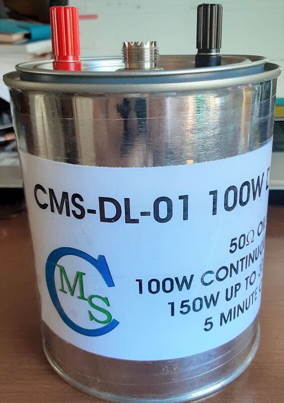
The paint can dummy load has been around for a long time. Most of them are based on the gallon-size paint can, which is rather large and awkward on the bench top. This article will describe the building of a quart-can size dummy load capable of sinking a full one hundred watts for two to three minutes, and one hundred fifty watts for up to thirty seconds at a time, with a five minute cool-down between tests.
The reason that this is possible is due to the ongoing miniaturization of RoHS (Restriction of Hazardous Substances) components, which have led to an overall shrinking in most component sizes. The parts for this project are readily available from numerous sources, with a full parts list provided at the end of the article. Credit for this concept and the project overall must go to a gentleman who has now gone silent key - Ken Kemski, K4EAA. I have modified his design and build slightly to make the build a little bit easier. However, Ken’s XYL Barb is maintaining his website (https://www.k4eaa.com/parts.htm) for as long as she can, and she has a supply of the resistors and diode used in this build. I will provide that contact information later, as well as alternate source information in case Barb stops maintaining the site.
The heart of this project is a set of twenty 1kΩ 3W metal film resistors, which are preferred over wirewound due to their low-inductance nature. The added inductance of wirewound resistors is best avoided when building a dummy load, as the inductance will affect the performance of the load. The resistors are connected in parallel to provide the nominal 50Ω input impedance of the dummy load. Ken’s design used 5% resistors, whereas I thought to use 1% tolerance devices instead. However, when I measured the actual resistance of my twenty-resistor parallel bundle using the 5% resistors, it measured out at 49.7 ohms, close enough to fifty ohms for anyone.
Whereas Ken’s original design used brass plates at either end of the resistor bundle, I switched off to 24-gauge copper plates instead, for several reasons :
This project can be built with either a BNC connector or a standard SO-239, at the choice of the builder. I already had an N and a BNC dummy load, so I made this one with the SO-239 connector.
The parts required for the build are :
The optional items are to allow auxiliary measurements to be taken from the dummy load, such as power measurements.
Start out by locating the center of the paint can lid and drilling a hole there to accommodate your bulkhead connector. A step bit is useful for this task. If you are going to install the optional diode and binding posts, now is the time to drill a pair of holes, one on either side of the center hole, of a size to accommodate the outer diameter of the threads of the binding posts. NOTE : These holes will need to be about 2-1/2” apart to allow the binding posts to clear the copper plate to which the resistors will be mounted.
Next, drill the same size hole as the center hole above in the center of one of the two 1.875” x 1.875” copper plates. This will be the ground side of the resistor bundle, and it will be mounted to the bulkhead connector. Now, on the copper blank with the hole drilled in it, lay out twenty hole centers in two concentric rings of ten holes each, with the inner ring holes staged between the outer ring holes as per the drawing in Figure 1.
The large circles in Figure 1 are shown just for clarity’s sake - to show the placement of the two rings of holes. These holes should be 1/16” in diameter - they are for the resistor leads, which should measure somewhere around 0.030” in diameter. After laying out the holes, center punch them and then clamp the two plates together and drill the holes through both plates at the same time. Then, with a hacksaw or bandsaw, cut off all four corners of each plate outboard of the drilled holes. This makes it easier to insert the assembled frame into the paint can. Finally, in the copper plate without the large center hole, drill the center location to 3/32” to accept the connection from the center of the BNC or SO-239 bulkhead connector.
Alternate Plate Prep Method
There is an alternate method of laying out and drilling the resistor holes in the copper plates, which is actually the method that I employed in this build. It involves printing a pair of the Figure 1 images at two adjacent corners of a 6” x 6” square, as shown in Figure 2. Once printed, measure the dimensions of the large outside square. It should be exactly 6” x 6”. If it is not, you will need to adjust your printer scaling and reprint the template. Refer to the section of the article headed “Adjusting Template Print Ratios” for scaling help. Once you have got a full-size print, continue from this point.
Wrap the print around one of the 6” x 6” copper sheets, aligning the printed pattern with one of the edges of the plate. Tape it in place. Then, using a center punch, transfer each of the resistor hole markings to the copper plate. Also transfer the center point markings of the patterns to the plate. Remove the pattern sheet from the plate and proceed to drill each of the marked centers with a 1/16” twist drill. After that, enlarge the center hole of one of the patterns to the correct size to accommodate the bulkhead connector, and drill out the center hole of the second plate to 3/32”. Once all of the drilling is done, cut the 1.875” x 1.875” plates from the overall 6” x 6” master plate. On each of the 1.875” x 1.875” plates, make a mark at about 0.300” from the corner at every edge of the plate, making two marks for each corner. Using a fine Sharpie® marker, connect the marks at each corner, creating trim lines at each corner of each plate. Using the cutting tool of your choice, cut off each corner of each plate along these lines.
Assembly Procedure
Remove the nut, washer, and ground lug from the bulkhead connector, and then insert the bulkhead connector into the hole in the paint can lid. Carefully solder all the way around the connector, sealing it to the can lid. This will take a heavier soldering gun than your normal pencil iron in most cases. After the can lid has cooled, place an o-ring onto each of the binding post bodies and install them through the can lid, securing them in place with their nuts. Take care not to squeeze the o-rings out of position when tightening the nuts. Connect and solder the cathode end of the BAV21 diode to the red binding post, and connect and solder one end of a stripped and tinned 3-1/2” length of 18AWG hook-up wire to the black binding post. If you are using stranded hook-up wire, tin the wire for its entire length. Cut this lead off at about 3/4” long and reserve the cut-off length for later use. Solder the ground lug to the hook-up wire stub from the black binding post.
Next, begin inserting and soldering the resistors to the copper plate with the large center hole. To provide additional cooling space between the resistors, slide the inner ring of resistors further into the copper plate, by a little bit more than the length of the resistor body. After soldering them in place, clip off the extra lead length above the copper plate. Then, when the outer ring’s resistors are inserted, insert just enough of each lead’s length to bend it over and solder it in place. This will stagger the spacing of the resistors lengthwise in the assembled frame.
Place the thin washer onto the bulkhead connector, and then place the plate and resistor assembly there, followed by the ground lug. Secure it all with the nut, rotating the plate so that the flat edges of the plate index towards the binding posts, and positioning the ground lug so that it is between two of the resistors. Make sure that the lead and lug do not come into contact with any resistor leads. Solder the reserved length of 18 AWG hook-up wire to the center terminal of the bulkhead connector.
Now it is time to begin installing the second end plate. One by one, insert the resistor leads into the plate, bending them over to keep them in place and to aid in soldering. Do not solder anything yet. Once you have all twenty resistors inserted into the plate, make sure that the plate is straight across at the bottom, adjusting its position on the resistors if necessary. Also make sure that the center lead of the bulkhead connector is passing through the center hole of the copper plate. Ten of the leads should project farther through the plate than the other ten do. Clip each lead off to about 1/8” above the copper plate, and then bend over all of the leads against the plate. Connect the anode end of the BAV21 diode to one of the resistor leads below the resistor body at the end plate. Solder all of the leads to the copper plate and the diode lead to the resistor lead.
Bear in mind that it will take a strong soldering iron to solder all of this together, because the copper plate will sink the heat so rapidly. I used my Weller 200W/260W gun for everything except the ground lug, the binding posts, and the diode anode lead. My 40W pencil iron on my soldering station could not put enough heat in quickly enough to get the solder to bond to the copper plate. I had it set at 852°F, but it was a no-go, so I got out the big boy.
Fill the paint can to within 1/4” of the top with mineral oil. Insert the assembled frame and seal the can. If desired, apply a label to the outside of the paint can. The dummy load is now ready to use.
Power Measurement
The installation of the BAV21 diode and the binding posts allows the user to measure the output power going into the dummy load with a voltmeter. Start by connecting a 0.01µF 250V ceramic disc capacitor across the binding posts. Because of the binding post spacing, I extended the capacitor lead length with some short lengths of solid hook-up wire. Now, with the dummy load connected to a radio and the mic keyed up, measure the voltage across the binding posts and record the reading. We have a little bit of math to do to get the measured power.
Suppose your reading was 99.6 Volts. Add in the 0.4V forward voltage drop across the BAV21 diode and we get 100.0V. It is always necessary to add the voltage drop of the diode to your measured voltage to get the actual voltage developed across the dummy load. Next, we have to divide the measured voltage by 1.414 (the square root of 2) to convert the peak voltage measured to an RMS voltage.
100 / 1.414 = 70.72VP
We square the RMS voltage and divide that value by the load impedance to get the power. Our load impedance is 50 ohms so…
(70.72 x 70.72) / 50 = POWER
Or, re-written…
5,001.3184 / 50 = POWER
Or, finally…
5,001.3184 / 50 = 100.026368W
Another example…suppose we measure 65.1v across the binding posts. Rounding to three decimal places, we get…
65.1 + 0.4 = 65.5V
65.5 / 1.414 = 46.323VP
(46.323 x 46.323) / 50 = POWER
2,145.820 / 50 = POWER
2,145.820 / 50 = 42.916W
Adjusting Template Print Ratios
If you are reading this section, it is most likely because the templates did not print out at their correct or required size. This probably results from printer scaling, or the adjustment of the size of the printed output by the printer driver software. The question, of course, is how do we resolve this issue so that we can print a full-size template? In most cases, it is pretty simple. Explore your printer properties dialog, looking for the section labeled Printer Scaling. Make sure that the scaling feature is set to 100% or to 1:1, whichever method is used. If the setting was NOT set at 100% or its equivalent, set it and reprint the templates. Measure the first one and see if it comes out as 6” x 6” (152.4mm x 152.4mm). If it does, all is well and you can move on with the rest of the prep and assembly.
If, however, your reprinted template print does NOT measure 6” x 6” (152.4mm x 152.4mm), you will need to determine the correct scale factor to apply to get your printer to print what we need. Suppose your template measures 5.4” x 5.4” (137.16mm x 137.16mm). What scale factor would we need? The formula needed is SPEC ÷ ACTUAL = SCALE. In this case, SPEC is 6.0” and ACTUAL is 5.4”. That gives us 6 ÷ 5.4 = SCALE, or 6 ÷ 5.4 = 1.1111. Thus, we would set the printer scale setting to 111.11%... 5.4 x 1.1111 = 5.9999, or 6 inches for all practical purposes.
So, what happens if the original printed template is larger than specified? Again, its easy, and the formula is the same. Suppose your print came out as 6.4” x 6.4”... 6 ÷ 6.4 = 0.9375. Thus, we would set the printer scale setting to 93.75%... 6.4 x 0.9375 = 6.000, or just what we are looking for.
For my network here, the default printer set up on this machine is the Brother HL-3170CDW. Figure 3 depicts the Advanced tab of the Printer Properties Sheet for that printer. It shows that the scaling feature is turned off, but that it can easily be set to scale the print output to a specific paper size (in this case, Letter size is shown) or to any free setting between 25% and 400%. Your printer’s properties dialog should have a similar setting. You may have to explore the various property sheet tabs to locate the setting, but you should find it there somewhere.
Parts List :
By Chris Prioli, AD2CS
The paint can dummy load has been around for a long time. Most of them are based on the gallon-size paint can, which is rather large and awkward on the bench top. This article will describe the building of a quart-can size dummy load capable of sinking a full one hundred watts for two to three minutes, and one hundred fifty watts for up to thirty seconds at a time, with a five minute cool-down between tests.
The reason that this is possible is due to the ongoing miniaturization of RoHS (Restriction of Hazardous Substances) components, which have led to an overall shrinking in most component sizes. The parts for this project are readily available from numerous sources, with a full parts list provided at the end of the article. Credit for this concept and the project overall must go to a gentleman who has now gone silent key - Ken Kemski, K4EAA. I have modified his design and build slightly to make the build a little bit easier. However, Ken’s XYL Barb is maintaining his website (https://www.k4eaa.com/parts.htm) for as long as she can, and she has a supply of the resistors and diode used in this build. I will provide that contact information later, as well as alternate source information in case Barb stops maintaining the site.
The heart of this project is a set of twenty 1kΩ 3W metal film resistors, which are preferred over wirewound due to their low-inductance nature. The added inductance of wirewound resistors is best avoided when building a dummy load, as the inductance will affect the performance of the load. The resistors are connected in parallel to provide the nominal 50Ω input impedance of the dummy load. Ken’s design used 5% resistors, whereas I thought to use 1% tolerance devices instead. However, when I measured the actual resistance of my twenty-resistor parallel bundle using the 5% resistors, it measured out at 49.7 ohms, close enough to fifty ohms for anyone.
Whereas Ken’s original design used brass plates at either end of the resistor bundle, I switched off to 24-gauge copper plates instead, for several reasons :
- Copper is easier to drill
- Copper is less expensive
- Copper is more readily available
This project can be built with either a BNC connector or a standard SO-239, at the choice of the builder. I already had an N and a BNC dummy load, so I made this one with the SO-239 connector.
The parts required for the build are :
- Quart-size paint can, available from most hardware stores
- Bulkhead connector of your choice for the cable connection
- Pair of 1.875” x 1.875” 24-gauge (0.051”) copper plates
- Twenty 1kΩ 3W metal film resistors, 1% is great, but 5% is OK
- BAV21 diode (optional)
- Pair of binding posts (one red & one black) (optional)
- Pair of o-rings to fit the binding posts (optional)
- Two pints of mineral oil
- 18 AWG hook-up wire
The optional items are to allow auxiliary measurements to be taken from the dummy load, such as power measurements.
Start out by locating the center of the paint can lid and drilling a hole there to accommodate your bulkhead connector. A step bit is useful for this task. If you are going to install the optional diode and binding posts, now is the time to drill a pair of holes, one on either side of the center hole, of a size to accommodate the outer diameter of the threads of the binding posts. NOTE : These holes will need to be about 2-1/2” apart to allow the binding posts to clear the copper plate to which the resistors will be mounted.
Next, drill the same size hole as the center hole above in the center of one of the two 1.875” x 1.875” copper plates. This will be the ground side of the resistor bundle, and it will be mounted to the bulkhead connector. Now, on the copper blank with the hole drilled in it, lay out twenty hole centers in two concentric rings of ten holes each, with the inner ring holes staged between the outer ring holes as per the drawing in Figure 1.
The large circles in Figure 1 are shown just for clarity’s sake - to show the placement of the two rings of holes. These holes should be 1/16” in diameter - they are for the resistor leads, which should measure somewhere around 0.030” in diameter. After laying out the holes, center punch them and then clamp the two plates together and drill the holes through both plates at the same time. Then, with a hacksaw or bandsaw, cut off all four corners of each plate outboard of the drilled holes. This makes it easier to insert the assembled frame into the paint can. Finally, in the copper plate without the large center hole, drill the center location to 3/32” to accept the connection from the center of the BNC or SO-239 bulkhead connector.
Alternate Plate Prep Method
There is an alternate method of laying out and drilling the resistor holes in the copper plates, which is actually the method that I employed in this build. It involves printing a pair of the Figure 1 images at two adjacent corners of a 6” x 6” square, as shown in Figure 2. Once printed, measure the dimensions of the large outside square. It should be exactly 6” x 6”. If it is not, you will need to adjust your printer scaling and reprint the template. Refer to the section of the article headed “Adjusting Template Print Ratios” for scaling help. Once you have got a full-size print, continue from this point.
Wrap the print around one of the 6” x 6” copper sheets, aligning the printed pattern with one of the edges of the plate. Tape it in place. Then, using a center punch, transfer each of the resistor hole markings to the copper plate. Also transfer the center point markings of the patterns to the plate. Remove the pattern sheet from the plate and proceed to drill each of the marked centers with a 1/16” twist drill. After that, enlarge the center hole of one of the patterns to the correct size to accommodate the bulkhead connector, and drill out the center hole of the second plate to 3/32”. Once all of the drilling is done, cut the 1.875” x 1.875” plates from the overall 6” x 6” master plate. On each of the 1.875” x 1.875” plates, make a mark at about 0.300” from the corner at every edge of the plate, making two marks for each corner. Using a fine Sharpie® marker, connect the marks at each corner, creating trim lines at each corner of each plate. Using the cutting tool of your choice, cut off each corner of each plate along these lines.
Assembly Procedure
Remove the nut, washer, and ground lug from the bulkhead connector, and then insert the bulkhead connector into the hole in the paint can lid. Carefully solder all the way around the connector, sealing it to the can lid. This will take a heavier soldering gun than your normal pencil iron in most cases. After the can lid has cooled, place an o-ring onto each of the binding post bodies and install them through the can lid, securing them in place with their nuts. Take care not to squeeze the o-rings out of position when tightening the nuts. Connect and solder the cathode end of the BAV21 diode to the red binding post, and connect and solder one end of a stripped and tinned 3-1/2” length of 18AWG hook-up wire to the black binding post. If you are using stranded hook-up wire, tin the wire for its entire length. Cut this lead off at about 3/4” long and reserve the cut-off length for later use. Solder the ground lug to the hook-up wire stub from the black binding post.
Next, begin inserting and soldering the resistors to the copper plate with the large center hole. To provide additional cooling space between the resistors, slide the inner ring of resistors further into the copper plate, by a little bit more than the length of the resistor body. After soldering them in place, clip off the extra lead length above the copper plate. Then, when the outer ring’s resistors are inserted, insert just enough of each lead’s length to bend it over and solder it in place. This will stagger the spacing of the resistors lengthwise in the assembled frame.
Place the thin washer onto the bulkhead connector, and then place the plate and resistor assembly there, followed by the ground lug. Secure it all with the nut, rotating the plate so that the flat edges of the plate index towards the binding posts, and positioning the ground lug so that it is between two of the resistors. Make sure that the lead and lug do not come into contact with any resistor leads. Solder the reserved length of 18 AWG hook-up wire to the center terminal of the bulkhead connector.
Now it is time to begin installing the second end plate. One by one, insert the resistor leads into the plate, bending them over to keep them in place and to aid in soldering. Do not solder anything yet. Once you have all twenty resistors inserted into the plate, make sure that the plate is straight across at the bottom, adjusting its position on the resistors if necessary. Also make sure that the center lead of the bulkhead connector is passing through the center hole of the copper plate. Ten of the leads should project farther through the plate than the other ten do. Clip each lead off to about 1/8” above the copper plate, and then bend over all of the leads against the plate. Connect the anode end of the BAV21 diode to one of the resistor leads below the resistor body at the end plate. Solder all of the leads to the copper plate and the diode lead to the resistor lead.
Bear in mind that it will take a strong soldering iron to solder all of this together, because the copper plate will sink the heat so rapidly. I used my Weller 200W/260W gun for everything except the ground lug, the binding posts, and the diode anode lead. My 40W pencil iron on my soldering station could not put enough heat in quickly enough to get the solder to bond to the copper plate. I had it set at 852°F, but it was a no-go, so I got out the big boy.
Fill the paint can to within 1/4” of the top with mineral oil. Insert the assembled frame and seal the can. If desired, apply a label to the outside of the paint can. The dummy load is now ready to use.
Power Measurement
The installation of the BAV21 diode and the binding posts allows the user to measure the output power going into the dummy load with a voltmeter. Start by connecting a 0.01µF 250V ceramic disc capacitor across the binding posts. Because of the binding post spacing, I extended the capacitor lead length with some short lengths of solid hook-up wire. Now, with the dummy load connected to a radio and the mic keyed up, measure the voltage across the binding posts and record the reading. We have a little bit of math to do to get the measured power.
Suppose your reading was 99.6 Volts. Add in the 0.4V forward voltage drop across the BAV21 diode and we get 100.0V. It is always necessary to add the voltage drop of the diode to your measured voltage to get the actual voltage developed across the dummy load. Next, we have to divide the measured voltage by 1.414 (the square root of 2) to convert the peak voltage measured to an RMS voltage.
100 / 1.414 = 70.72VP
We square the RMS voltage and divide that value by the load impedance to get the power. Our load impedance is 50 ohms so…
(70.72 x 70.72) / 50 = POWER
Or, re-written…
5,001.3184 / 50 = POWER
Or, finally…
5,001.3184 / 50 = 100.026368W
Another example…suppose we measure 65.1v across the binding posts. Rounding to three decimal places, we get…
65.1 + 0.4 = 65.5V
65.5 / 1.414 = 46.323VP
(46.323 x 46.323) / 50 = POWER
2,145.820 / 50 = POWER
2,145.820 / 50 = 42.916W
Adjusting Template Print Ratios
If you are reading this section, it is most likely because the templates did not print out at their correct or required size. This probably results from printer scaling, or the adjustment of the size of the printed output by the printer driver software. The question, of course, is how do we resolve this issue so that we can print a full-size template? In most cases, it is pretty simple. Explore your printer properties dialog, looking for the section labeled Printer Scaling. Make sure that the scaling feature is set to 100% or to 1:1, whichever method is used. If the setting was NOT set at 100% or its equivalent, set it and reprint the templates. Measure the first one and see if it comes out as 6” x 6” (152.4mm x 152.4mm). If it does, all is well and you can move on with the rest of the prep and assembly.
If, however, your reprinted template print does NOT measure 6” x 6” (152.4mm x 152.4mm), you will need to determine the correct scale factor to apply to get your printer to print what we need. Suppose your template measures 5.4” x 5.4” (137.16mm x 137.16mm). What scale factor would we need? The formula needed is SPEC ÷ ACTUAL = SCALE. In this case, SPEC is 6.0” and ACTUAL is 5.4”. That gives us 6 ÷ 5.4 = SCALE, or 6 ÷ 5.4 = 1.1111. Thus, we would set the printer scale setting to 111.11%... 5.4 x 1.1111 = 5.9999, or 6 inches for all practical purposes.
So, what happens if the original printed template is larger than specified? Again, its easy, and the formula is the same. Suppose your print came out as 6.4” x 6.4”... 6 ÷ 6.4 = 0.9375. Thus, we would set the printer scale setting to 93.75%... 6.4 x 0.9375 = 6.000, or just what we are looking for.
For my network here, the default printer set up on this machine is the Brother HL-3170CDW. Figure 3 depicts the Advanced tab of the Printer Properties Sheet for that printer. It shows that the scaling feature is turned off, but that it can easily be set to scale the print output to a specific paper size (in this case, Letter size is shown) or to any free setting between 25% and 400%. Your printer’s properties dialog should have a similar setting. You may have to explore the various property sheet tabs to locate the setting, but you should find it there somewhere.
Parts List :
- (1) Quart paint can with steel lid - Ace or True Value hardware stores
- (1) SO-239 Bulkhead Connector - Amazon, search “SO-239 bulkhead connector”
- (1) BNC Bulkhead Connector - Jameco 71590 (alternate)
- (20) Resistors - 1kΩ 3W Metal Film 5% - Mouser 603-FMP300JR-73-1K
- (1 Kit) Resistors - 1kΩ 3W Metal Film 5% - https://www.k4eaa.com/parts.htm - scroll down on page - Kit includes BAV21 diode (alternate)
- (20) Resistors - 1kΩ 3W Metal Film 1% - Mouser 71-CPF3-F-1K/R (alternate)
- (1) Diode - BAV21 - Mouser 78-BAV21 (optional equipment)
- (1 pair) Binding Posts - Jameco 77691 (pair 1 red 1 black) (optional equipment)
- (1 pair) O-rings - hardware store - size to fit actual binding post - 1.5mm stock, probably 8mm ID (optional equipment)
- (1 quart) Mineral Oil - hardware store or pharmacy
- (1) Copper Plate 6” x 6” x 24 gauge - hardware store or Amazon (search “copper sheet”)