|
1.25M (220 MHz)
|
1.25M Homebrew J-Pole Antenna
By Chris Prioli, AD2CS
I recently purchased a new radio to add to my shack, a TYT TH9000D 1.25-meter mobile unit (Figure 1) that will be used as a base station. To support the new radio, I also purchased a Comet CX-333 tri-band vertical antenna, which is designed to cover the 2-meter, 1.25-meter, and 70-centimeter bands. However, I also wanted a dedicated antenna for the 1.25-meter band, so I decided to build one rather than buy it premade. I am sure that this subject has been done to death, but I am going to have a go at it anyway, so please bear with me and hang on for the ride!
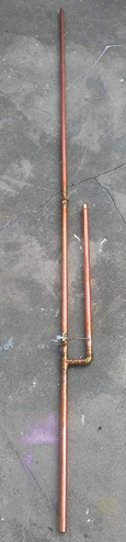
I chose copper pipe construction (Figure 2) for several reasons :
Every piece of this antenna except for the feed point connector is available at any hardware store, from a mom-and-pop to a big-box location. The feed point connector is readily available online, from a multitude of sources.
The following is a list of the required component parts :
In addition, some supplies will be needed, which also are available at the hardware store :
Some special tools will also be needed or very helpful :
For those who may be unfamiliar with the term, a “v-block” is a short length of plastic, wooden or metallic material with a “V” shaped groove along its length in its upper surface, designed to be affixed to a drill press table. It is used to hold round stock securely for drilling or cutting. By use of a v-block, holes perpendicular to the length of a pipe can accurately be drilled through the pipe’s diameter. The better v-blocks will have a drill clearance slot in the bottom of the groove as well as mounting provisions, e.g., a pair of flanges, for easy securement to the drill press table or work bench top surface. My v-block (Figure 3) is a length of aluminum extrusion with a flanged lower surface and angular upper flanges forming the “V” that supports the round stock. The bottom of the “V” contains a groove to allow full drill-through of the stock and also to aid in centering the v-block under the drill spindle for accuracy. The lower (mounting) flanges are notched to accept hold-down bolts.
It is very convenient that the total length of copper pipe required for this project is exactly sixty inches, the equivalent of a five-foot length of pipe. This is convenient because the pipe is generally sold in five- and ten-foot lengths as well as some lengths shorter than the five-foot ones. I purchased a five-footer at my local Home Depot store for this project. In fact, all of the copper needed for this project came from the Home Depot in a single order that totaled a penny more than eighteen dollars. All of the other parts and supplies needed are on hand in my shop, as are all of the needed tools.
A Pipe/Tubing Cutter (Figure 4) is preferred over a saw of any kind for cutting the copper pipe to length. This is because the tube cutter makes a clean and non-deforming cut that has zero length loss (no kerfs width or copper sawdust) and is always perfectly square to the tube. Half-inch copper pipe can be cut with either the mini-cutter used for smaller tubes or the next size up, which will cut tubing up to two inches or so in diameter. These cutters work by bringing a cutter wheel up against the tube surface at the cut point and then rotating the cutter around the pipe, with the pipe pressed between two rollers and the cutter wheel, and gradually tightening up on the cutter wheel force as you run the cutter around the pipe. This rotate - tighten - rotate process is continued, with the tightening being done in small increments as you go, until the pipe is parted. There may be a small burr along the cut edges of both pipe sections, easily removable with the de-burr blade that is mounted on the tube cutter frame for the larger cutters, or is a separate tool in the case of the mini cutters. A pocket knife will also do the job nicely.
While this article provides the instructions and dimensions for fabricating a 1.25-meter antenna, these plans, with some minor modifications as to pipe lengths, can be used to build a J-pole for most any of the ham bands. There is a standard formula (Figure 5) that is applied to derive the various cut lengths for the copper pipe, as follows :
Note that the inter-element spacing is the distance between the pipes, not their center-to-center pitch, and that the feed point distance is its location above the center of the tee.
Applying the standards from the illustration or the text above, and based on the center of the 1.25-meter band at 222MHz, we would get the following dimensions :
I did some rounding to get lengths that would work together to fit the entire project into a single five-foot length of pipe, purely for purchase and cutting convenience. Actual final element lengths are adjusted by use of brass screws installed into the copper pipe caps, as we will discuss shortly.
Once all of the component parts, needed supplies, and appropriate tools are gathered together, it is time to begin the actual build of the antenna. We will begin by cutting all of the required copper pipe lengths. I found it easier to measure and mark the pipe at the various cut points, starting with the shortest required length of one inch (1”). After that, cut a piece that is twelve and one-half inches (12-1/2”) long. Finally, the thirty-eight and one-quarter inches (38-1/4”) piece was cut, leaving eight and one-quarter inches (8-1/4”) of leftover pipe (Figure 6), which is installed as the mounting stub below the J-pole proper.
Next up is the preparation of the pipe and the pipe fittings for sweating. “Sweating” is the term used for the process of soldering pipe and pipe fittings together. This is a skill that takes a little bit of practice before one feels comfortable in performing the task. However, once the skill is developed, it is not soon forgotten. The trick in sweating pipe is to have clean joining surfaces, use adequate flux, and apply only enough heat to get the job done.
It is important that the heat is not excessive, as too much heat will cause physical changes in the metal that will make it almost impossible to successfully join the pipe and fitting. Light heat, moving quickly across the joint and heating the joint just below the point where the solder will be introduced is the best method. Let the heat of the metal melt the solder and draw it into the joint.
Cleaning the pipe and fittings before sweating is a very important step and must not be overlooked. Clean the inside joining surfaces of your pipe fittings using the wire bottle brush or some emery cloth, making sure to then clean out any dust formed by the cleaning process. Clean the outside of the pipe ends that will be joined by scrubbing the pipe with emery cloth. Again, be sure to remove any dust particles that may have resulted from the cleaning process. I actually have a very handy tool that is a dual wire brush (Figure 7), bottle brushes on each end and a pair of hollow circular brushes in the center. The bottle brush cleans the inside of the fittings and the hollow circular brush cleans the outside of the pipe.
Another important preparatory step is to make some modifications to the 1/2” copper pipe caps. If the caps that you purchase are domed slightly, as mine were, you will need to “flatten” the dome on each cap. There are two easy ways to do this. One way is to place the cap on the anvil step of your bench vise and then use a hammer and a small piece of hardwood (oak, maple, etc.) to flatten the dome via impact. The other easy way is to sandwich the pipe cap between two pieces of hardwood in the jaws of your bench vise and use the vise as a press to flatten the dome. Once the dome has been flattened, ascertain that the cap will still fit on the pipe properly. Then, take the cap off the pipe and mark the center of the flattened end of the cap. Center-punch this mark, and then drill a 5/32” hole at that center-punched mark. Now install a 6-32 x 3/8” plated machine screw and a 6-32 brass hex nut to each copper pipe cap. The screw must be installed in such a manner that the head of the screw is inside the pipe cap, and the nut is just snug enough to be held flat against the surface of the pipe cap (Figure 8). These screws are for clamping purposes only and will be removed from the outside later, dropping through the pipe. This is to be done to both of the 1/2" copper pipe caps.
Before sweating any pipe, dry fit all of the pieces so that :
To dry-fit the antenna’s parts, start by inserting the 1” pipe into one end of the elbow and the other end of the 1” pipe into the center port of the tee, positioning the fittings so that the second port of the elbow is parallel to the top end of the tee, and that the assembly lies flat on the work surface with all of the pipe or fitting openings in a common plane. Insert the 12-1/2” pipe into the second port of the elbow, again ensuring that the assembly still lies flat when it is laid on the bench top with the tee at the left side. Insert the 38-1/4” pipe into the end of the tee that would place this pipe next to and parallel to the 12-1/2’ pipe. Insert the 7-1/4” pipe into the opposite end of the tee. Place a cap on the open ends of the 12-1/2” and the 38-1/4” pipes.
Apart from the feed point connector and center feed wire, this is what the antenna will look like when it is complete. Make sure that all of the parts are positioned so that the assembly lies flat and square on the work surface (Figure 9). When sweating the pipes and fittings, it is important to maintain the positions of all of these parts in one single plane.
After you are satisfied with the fit and form of the antenna, it is time to start sweating fittings onto the pipes. The sequence of assembly is not important. What is of paramount importance is the proper positioning of the elbow and tee, so that the assembly is all in a single plane and that the two longest pipes are parallel to each other. Be sure to sweat the caps onto the two longest pipes only. The appearance of the sweated joint can be improved greatly by wiping the joint with a rag soaked with cold water while the joint is still hot.
When all of the sweating is completed, allow the assembly to cool, and then clean it thoroughly with water inside and out, using some mild dish soap if necessary to remove all traces of the solder flux that may remain on the copper. After a thorough final rinse, shake out as much water as possible from inside the pipes, and towel dry the outside of the pipes.
Now, working quickly, using rosin core solder and applying the heat carefully so as not to loosen the pipe caps, solder each of the brass nuts on the outside of the pipe caps directly to the pipe caps themselves, taking care not to get any solder on the threads. After soldering the nuts in place, allow the assembly to cool completely, and then remove the plated screws from the soldered brass nuts, allowing the screws to drop into the pipes. A pair of pliers will start the screws turning, and then the tip of a jeweler’s screwdriver or an awl can be used to continue turning the screws (Figure 10). If the screws are stubborn, a hand drill with a small twist drill can also be used to spin the screws out. Start the twist drill into the center of the screw, and then run the drill slowly. As the twist drill bites into the screw, the screw will be spun out. Move the assembly as necessary to get both screws to travel through and out of the pipes.
Once the plated screws have fallen out of the antenna, install a 6-32 brass hex nut to each of the 6-32 x 1-1/2” brass machine screws, and then thread one of these brass screws into the brass nut soldered to each of the antenna’s copper pipe caps. Snug the upper nuts down against the soldered nuts to lock the brass screws in position. The brass screws are used to adjust the SWR of the antenna by changing the electrical length of the antenna’s elements.
It is now time to talk about installation of the feed point connector. I chose to install an SO-239 flange-mount panel jack. This jack has a square mounting flange with a screw hole in each corner (Figure 11). We are going to use only one of these mounting holes, but before we can mount the SO-239 to the pipe, we have to drill a hole in the pipe. The placement of this hole is important, so measure carefully.
Position the assembly in your v-block with the 12-1/2” pipe down and the 38-1/4” pipe up. Clamp the assembly in that position, so that the longest pipe is at the top and towards the drill spindle. Measure and mark a point on the 38-1/4” pipe 1-1/4” from the end of the pipe tee. Center punch that point, and then drill a 1/8” hole in the pipe’s upper surface only.
Position the assembly flat on the work surface with the newly-drilled hole towards you. Place the SO-239 flange over the drilled hole with the body of the SO-239 above the pipe and one corner hole aligned over the drilled hole in the pipe. Secure the SO-239 to the pipe with a 1/8’ pop rivet having a grip range of about 3/16” to 1/4". Next, using either the propane torch or a high-wattage soldering gun, solder the flange of the SO-239 to the copper pipe (Figure 12), using rosin core solder only. Work quickly and carefully so as not to melt the center insulator of the SO-239 connector. This is not a real issue if the SO-239 is Teflon®-insulated.
Next, we have to drill another hole, this one in the 12-1/2” pipe but on the side of the pipe that would be at the top if the antenna assembly was to be laid flat on the work surface with the flange of the SO-239 in a vertical orientation. This hole will be 1/8” and is to be on the 12-1/2” pipe directly across from the center terminal solder cup of the SO-239 jack (Figure 13). This hole should then fall at a distance of 1-1/4” from the end of the elbow that supports the 12-1/2” pipe.
After drilling the 1/8” hole in the 12-1/2” pipe, locate the 2” length of bare 10 AWG solid copper wire. Make a 90° bend in this wire at approximately 1/4" from one end (Figure 14). The idea is to bend this wire in such a manner that it will just fit between the center terminal solder cup of the SO-239 while the bent end fits into the 1/8” hole in the 12-1/2” pipe. Once you have the wire bent to fit properly (Figure 15), insert it into place and solder it there, again using only rosin core solder. If necessary, trim the long end of the wire until it fits properly between the drilled hole and the SO-239 center conductor solder cup.
Now it is time to install some protective coating to the SO-239 center terminal solder cup. This can easily be done using a liquid electrical tape product such as Gardner Bender LTB-400 Liquid Tape. This product is available in other colors besides the standard black, though the black variety has always worked well for me.
Another excellent choice is to make a flowable sealant from some 100% silicon sealant such as the GE Advanced Silicone 2® (Figure 16) and a small amount of mineral spirits. Here is the process for making this sealant into a flowable, self-leveling mixture :
Apply this mixture to the area to be sealed, using a disposable acid brush as the spreading tool. The mixture will seek its own level and smooth itself over as it flows into place. Note that this mixture will cure much more rapidly than will the unadulterated silicone sealant, so work quickly to get it applied where and as desired. This mixture was introduced to me by Frank N3PUU, so I thank him for his contribution.
At this point, the antenna is ready for testing and adjustment, and then for installation and use. I tested mine with three different pieces of test equipment - my NanoVNA H4, my MFJ-259D SWR Analyzer, and my RigExpert® AA-650 ZOOM Antenna Analyzer. I got somewhat similar results from all three tests, and the data obtained was quite informative. Due to the differences in testing algorithms and methodologies, the obtained results were bound to show some differences. The funny thing is that for many of us (ham operators), we only have one piece of antenna test equipment, therefore, we would take a reading with that tester and call it a day. Our antennas are behaving like the tester that we have available says they are behaving, right? So what happens when we do have multiple testers? Which one is the correct reading? The answer is that they all are right, each in its own way. What is being said by each tester is that the antenna, when tested under the conditions existing at the time of the test, and under the specific testing methodology used for the test, and taking into consideration any inherent error in the tester and/or its methods when the test was performed, behaved as reported in the test results.
In the case of this newly-built antenna, the NanoVNA H4 (Figure 17), newly calibrated and set for a frequency sweep range of 200MHz to 230MHz and measuring 301 data points, reported the following results when set for SWR and a Smith Chart :
The same antenna, with the same length of RG-213 coaxial cable now connected to the MFJ-259D (Figure 18), came up with a 1.0:1 SWR, resistance of 50? and reactance of 0?, all at 221.86MHz.
When tested with the RigExpert AA-650 (Figure 19), it came up as 1.08:1 SWR and 53.1? impedance, but at 222.5MHz. This test further showed the complex impedance to be 53-j2.6?, with an inductive reactance component of -1.9nH and a capacitive reactance component of 275.6pF. Similar data is available from the NanoVNA if those options are selected.
This antenna was a very easy build, with the most difficult part for me being the sweating of the pipe and fittings, as I am not very proficient with a plumber’s torch. As was mentioned earlier, the basic antenna design can be adapted to virtually any band, while it is best suited for the short-wavelength bands. It is a simple matter of plugging in the design frequency into the formulas provided in the graphic in Figure 5.
Time will tell what the actual performance is like, when I get it installed and operational. I can make final SWR adjustments at that point, thanks to the adjustment screws on the pipe caps. The only question is, which tester will I use?
By Chris Prioli, AD2CS
I recently purchased a new radio to add to my shack, a TYT TH9000D 1.25-meter mobile unit (Figure 1) that will be used as a base station. To support the new radio, I also purchased a Comet CX-333 tri-band vertical antenna, which is designed to cover the 2-meter, 1.25-meter, and 70-centimeter bands. However, I also wanted a dedicated antenna for the 1.25-meter band, so I decided to build one rather than buy it premade. I am sure that this subject has been done to death, but I am going to have a go at it anyway, so please bear with me and hang on for the ride!
I chose copper pipe construction (Figure 2) for several reasons :
- Its simplicity.
- Its strength.
- Its low cost.
- Its compact nature.
Every piece of this antenna except for the feed point connector is available at any hardware store, from a mom-and-pop to a big-box location. The feed point connector is readily available online, from a multitude of sources.
The following is a list of the required component parts :
- 1/2" Type M copper pipe caps - 2 pieces
- 1/2" Type M copper pipe tee - 1 piece
- 1/2" Type M copper elbow 90° - 1 piece
- 1/2" Type M copper pipe 1" long - 1 piece (not exposed when assembled)
- 1/2" Type M copper pipe 8-1/4" long - 1 piece (7-3/4" exposed when assembled)
- 1/2" Type M copper pipe 12-1/2" long - 1 piece (11-1/2" exposed when assembled)
- 1/2" Type M copper pipe 38-1/4" long - 1 piece (37-1/4" exposed when assembled)
- 10AWG bare solid copper wire 2" long - 1 piece
- 6-32 x 1-1/2” brass machine screw – 2 pieces
- 6-32 x 3/8" plated machine screw – 2 pieces
- 6-32 brass hex nut – 4 pieces
- SO-239 connector, flange/panel mount, Teflon®-insulated recommended - 1 piece
- Aluminum pop rivet, 1/8" x 3/16" to 1/4" grip range - 1 piece
In addition, some supplies will be needed, which also are available at the hardware store :
- Emery or crocus cloth
- Plumber’s solder and flux
- Electronics (rosin-core) solder
- Liquid electrical tape (or alternative sealer - explained in detail later)
Some special tools will also be needed or very helpful :
- Tubing cutter
- Propane torch for sweating copper pipe and fittings
- High wattage soldering gun, 200/240 watts minimum
- Pop rivet gun
- Electric drill (drill press is ideal) with 1/8” and 5/32” twist drills
- Small wire bottle brush
- V-block for drilling round shapes
For those who may be unfamiliar with the term, a “v-block” is a short length of plastic, wooden or metallic material with a “V” shaped groove along its length in its upper surface, designed to be affixed to a drill press table. It is used to hold round stock securely for drilling or cutting. By use of a v-block, holes perpendicular to the length of a pipe can accurately be drilled through the pipe’s diameter. The better v-blocks will have a drill clearance slot in the bottom of the groove as well as mounting provisions, e.g., a pair of flanges, for easy securement to the drill press table or work bench top surface. My v-block (Figure 3) is a length of aluminum extrusion with a flanged lower surface and angular upper flanges forming the “V” that supports the round stock. The bottom of the “V” contains a groove to allow full drill-through of the stock and also to aid in centering the v-block under the drill spindle for accuracy. The lower (mounting) flanges are notched to accept hold-down bolts.
It is very convenient that the total length of copper pipe required for this project is exactly sixty inches, the equivalent of a five-foot length of pipe. This is convenient because the pipe is generally sold in five- and ten-foot lengths as well as some lengths shorter than the five-foot ones. I purchased a five-footer at my local Home Depot store for this project. In fact, all of the copper needed for this project came from the Home Depot in a single order that totaled a penny more than eighteen dollars. All of the other parts and supplies needed are on hand in my shop, as are all of the needed tools.
A Pipe/Tubing Cutter (Figure 4) is preferred over a saw of any kind for cutting the copper pipe to length. This is because the tube cutter makes a clean and non-deforming cut that has zero length loss (no kerfs width or copper sawdust) and is always perfectly square to the tube. Half-inch copper pipe can be cut with either the mini-cutter used for smaller tubes or the next size up, which will cut tubing up to two inches or so in diameter. These cutters work by bringing a cutter wheel up against the tube surface at the cut point and then rotating the cutter around the pipe, with the pipe pressed between two rollers and the cutter wheel, and gradually tightening up on the cutter wheel force as you run the cutter around the pipe. This rotate - tighten - rotate process is continued, with the tightening being done in small increments as you go, until the pipe is parted. There may be a small burr along the cut edges of both pipe sections, easily removable with the de-burr blade that is mounted on the tube cutter frame for the larger cutters, or is a separate tool in the case of the mini cutters. A pocket knife will also do the job nicely.
While this article provides the instructions and dimensions for fabricating a 1.25-meter antenna, these plans, with some minor modifications as to pipe lengths, can be used to build a J-pole for most any of the ham bands. There is a standard formula (Figure 5) that is applied to derive the various cut lengths for the copper pipe, as follows :
- Long element - 705’/frequencyMHz or 8460”/frequencyMHz
- Short element - 234’/frequencyMHz or 2808”/frequencyMHz
- Inter-element spacing - 22’/frequencyMHz or 264”/frequencyMHz
- Feed point location - 23’/frequencyMHz or 276”/frequencyMHz
Note that the inter-element spacing is the distance between the pipes, not their center-to-center pitch, and that the feed point distance is its location above the center of the tee.
Applying the standards from the illustration or the text above, and based on the center of the 1.25-meter band at 222MHz, we would get the following dimensions :
- Long element - 8460”/222MHz = 38.108”
- Short element - 2808”/222MHz = 12.649”
- Inter-element spacing - 264”/222MHz = 1.189”
- Feed point location - 276”/222MHz = 1.243”
I did some rounding to get lengths that would work together to fit the entire project into a single five-foot length of pipe, purely for purchase and cutting convenience. Actual final element lengths are adjusted by use of brass screws installed into the copper pipe caps, as we will discuss shortly.
Once all of the component parts, needed supplies, and appropriate tools are gathered together, it is time to begin the actual build of the antenna. We will begin by cutting all of the required copper pipe lengths. I found it easier to measure and mark the pipe at the various cut points, starting with the shortest required length of one inch (1”). After that, cut a piece that is twelve and one-half inches (12-1/2”) long. Finally, the thirty-eight and one-quarter inches (38-1/4”) piece was cut, leaving eight and one-quarter inches (8-1/4”) of leftover pipe (Figure 6), which is installed as the mounting stub below the J-pole proper.
Next up is the preparation of the pipe and the pipe fittings for sweating. “Sweating” is the term used for the process of soldering pipe and pipe fittings together. This is a skill that takes a little bit of practice before one feels comfortable in performing the task. However, once the skill is developed, it is not soon forgotten. The trick in sweating pipe is to have clean joining surfaces, use adequate flux, and apply only enough heat to get the job done.
It is important that the heat is not excessive, as too much heat will cause physical changes in the metal that will make it almost impossible to successfully join the pipe and fitting. Light heat, moving quickly across the joint and heating the joint just below the point where the solder will be introduced is the best method. Let the heat of the metal melt the solder and draw it into the joint.
Cleaning the pipe and fittings before sweating is a very important step and must not be overlooked. Clean the inside joining surfaces of your pipe fittings using the wire bottle brush or some emery cloth, making sure to then clean out any dust formed by the cleaning process. Clean the outside of the pipe ends that will be joined by scrubbing the pipe with emery cloth. Again, be sure to remove any dust particles that may have resulted from the cleaning process. I actually have a very handy tool that is a dual wire brush (Figure 7), bottle brushes on each end and a pair of hollow circular brushes in the center. The bottle brush cleans the inside of the fittings and the hollow circular brush cleans the outside of the pipe.
Another important preparatory step is to make some modifications to the 1/2” copper pipe caps. If the caps that you purchase are domed slightly, as mine were, you will need to “flatten” the dome on each cap. There are two easy ways to do this. One way is to place the cap on the anvil step of your bench vise and then use a hammer and a small piece of hardwood (oak, maple, etc.) to flatten the dome via impact. The other easy way is to sandwich the pipe cap between two pieces of hardwood in the jaws of your bench vise and use the vise as a press to flatten the dome. Once the dome has been flattened, ascertain that the cap will still fit on the pipe properly. Then, take the cap off the pipe and mark the center of the flattened end of the cap. Center-punch this mark, and then drill a 5/32” hole at that center-punched mark. Now install a 6-32 x 3/8” plated machine screw and a 6-32 brass hex nut to each copper pipe cap. The screw must be installed in such a manner that the head of the screw is inside the pipe cap, and the nut is just snug enough to be held flat against the surface of the pipe cap (Figure 8). These screws are for clamping purposes only and will be removed from the outside later, dropping through the pipe. This is to be done to both of the 1/2" copper pipe caps.
Before sweating any pipe, dry fit all of the pieces so that :
- You have a solid understanding of the location of each of the individual pieces
- All of the parts and pieces fit together properly.
To dry-fit the antenna’s parts, start by inserting the 1” pipe into one end of the elbow and the other end of the 1” pipe into the center port of the tee, positioning the fittings so that the second port of the elbow is parallel to the top end of the tee, and that the assembly lies flat on the work surface with all of the pipe or fitting openings in a common plane. Insert the 12-1/2” pipe into the second port of the elbow, again ensuring that the assembly still lies flat when it is laid on the bench top with the tee at the left side. Insert the 38-1/4” pipe into the end of the tee that would place this pipe next to and parallel to the 12-1/2’ pipe. Insert the 7-1/4” pipe into the opposite end of the tee. Place a cap on the open ends of the 12-1/2” and the 38-1/4” pipes.
Apart from the feed point connector and center feed wire, this is what the antenna will look like when it is complete. Make sure that all of the parts are positioned so that the assembly lies flat and square on the work surface (Figure 9). When sweating the pipes and fittings, it is important to maintain the positions of all of these parts in one single plane.
After you are satisfied with the fit and form of the antenna, it is time to start sweating fittings onto the pipes. The sequence of assembly is not important. What is of paramount importance is the proper positioning of the elbow and tee, so that the assembly is all in a single plane and that the two longest pipes are parallel to each other. Be sure to sweat the caps onto the two longest pipes only. The appearance of the sweated joint can be improved greatly by wiping the joint with a rag soaked with cold water while the joint is still hot.
When all of the sweating is completed, allow the assembly to cool, and then clean it thoroughly with water inside and out, using some mild dish soap if necessary to remove all traces of the solder flux that may remain on the copper. After a thorough final rinse, shake out as much water as possible from inside the pipes, and towel dry the outside of the pipes.
Now, working quickly, using rosin core solder and applying the heat carefully so as not to loosen the pipe caps, solder each of the brass nuts on the outside of the pipe caps directly to the pipe caps themselves, taking care not to get any solder on the threads. After soldering the nuts in place, allow the assembly to cool completely, and then remove the plated screws from the soldered brass nuts, allowing the screws to drop into the pipes. A pair of pliers will start the screws turning, and then the tip of a jeweler’s screwdriver or an awl can be used to continue turning the screws (Figure 10). If the screws are stubborn, a hand drill with a small twist drill can also be used to spin the screws out. Start the twist drill into the center of the screw, and then run the drill slowly. As the twist drill bites into the screw, the screw will be spun out. Move the assembly as necessary to get both screws to travel through and out of the pipes.
Once the plated screws have fallen out of the antenna, install a 6-32 brass hex nut to each of the 6-32 x 1-1/2” brass machine screws, and then thread one of these brass screws into the brass nut soldered to each of the antenna’s copper pipe caps. Snug the upper nuts down against the soldered nuts to lock the brass screws in position. The brass screws are used to adjust the SWR of the antenna by changing the electrical length of the antenna’s elements.
It is now time to talk about installation of the feed point connector. I chose to install an SO-239 flange-mount panel jack. This jack has a square mounting flange with a screw hole in each corner (Figure 11). We are going to use only one of these mounting holes, but before we can mount the SO-239 to the pipe, we have to drill a hole in the pipe. The placement of this hole is important, so measure carefully.
Position the assembly in your v-block with the 12-1/2” pipe down and the 38-1/4” pipe up. Clamp the assembly in that position, so that the longest pipe is at the top and towards the drill spindle. Measure and mark a point on the 38-1/4” pipe 1-1/4” from the end of the pipe tee. Center punch that point, and then drill a 1/8” hole in the pipe’s upper surface only.
Position the assembly flat on the work surface with the newly-drilled hole towards you. Place the SO-239 flange over the drilled hole with the body of the SO-239 above the pipe and one corner hole aligned over the drilled hole in the pipe. Secure the SO-239 to the pipe with a 1/8’ pop rivet having a grip range of about 3/16” to 1/4". Next, using either the propane torch or a high-wattage soldering gun, solder the flange of the SO-239 to the copper pipe (Figure 12), using rosin core solder only. Work quickly and carefully so as not to melt the center insulator of the SO-239 connector. This is not a real issue if the SO-239 is Teflon®-insulated.
Next, we have to drill another hole, this one in the 12-1/2” pipe but on the side of the pipe that would be at the top if the antenna assembly was to be laid flat on the work surface with the flange of the SO-239 in a vertical orientation. This hole will be 1/8” and is to be on the 12-1/2” pipe directly across from the center terminal solder cup of the SO-239 jack (Figure 13). This hole should then fall at a distance of 1-1/4” from the end of the elbow that supports the 12-1/2” pipe.
After drilling the 1/8” hole in the 12-1/2” pipe, locate the 2” length of bare 10 AWG solid copper wire. Make a 90° bend in this wire at approximately 1/4" from one end (Figure 14). The idea is to bend this wire in such a manner that it will just fit between the center terminal solder cup of the SO-239 while the bent end fits into the 1/8” hole in the 12-1/2” pipe. Once you have the wire bent to fit properly (Figure 15), insert it into place and solder it there, again using only rosin core solder. If necessary, trim the long end of the wire until it fits properly between the drilled hole and the SO-239 center conductor solder cup.
Now it is time to install some protective coating to the SO-239 center terminal solder cup. This can easily be done using a liquid electrical tape product such as Gardner Bender LTB-400 Liquid Tape. This product is available in other colors besides the standard black, though the black variety has always worked well for me.
Another excellent choice is to make a flowable sealant from some 100% silicon sealant such as the GE Advanced Silicone 2® (Figure 16) and a small amount of mineral spirits. Here is the process for making this sealant into a flowable, self-leveling mixture :
- Squirt a small amount, about the size of a large marble, into a suitable disposable mixing container such as a cut-down Solo™ cup.
- Add a quantity of mineral spirits that would make about a ten-to-one ratio of silicone sealant to mineral spirits.
- Thoroughly mix the two ingredients together until fully blended, adding small amounts of mineral spirits as required to achieve a flowable consistency.
Apply this mixture to the area to be sealed, using a disposable acid brush as the spreading tool. The mixture will seek its own level and smooth itself over as it flows into place. Note that this mixture will cure much more rapidly than will the unadulterated silicone sealant, so work quickly to get it applied where and as desired. This mixture was introduced to me by Frank N3PUU, so I thank him for his contribution.
At this point, the antenna is ready for testing and adjustment, and then for installation and use. I tested mine with three different pieces of test equipment - my NanoVNA H4, my MFJ-259D SWR Analyzer, and my RigExpert® AA-650 ZOOM Antenna Analyzer. I got somewhat similar results from all three tests, and the data obtained was quite informative. Due to the differences in testing algorithms and methodologies, the obtained results were bound to show some differences. The funny thing is that for many of us (ham operators), we only have one piece of antenna test equipment, therefore, we would take a reading with that tester and call it a day. Our antennas are behaving like the tester that we have available says they are behaving, right? So what happens when we do have multiple testers? Which one is the correct reading? The answer is that they all are right, each in its own way. What is being said by each tester is that the antenna, when tested under the conditions existing at the time of the test, and under the specific testing methodology used for the test, and taking into consideration any inherent error in the tester and/or its methods when the test was performed, behaved as reported in the test results.
In the case of this newly-built antenna, the NanoVNA H4 (Figure 17), newly calibrated and set for a frequency sweep range of 200MHz to 230MHz and measuring 301 data points, reported the following results when set for SWR and a Smith Chart :
- An SWR of 1.324:1 at 225MHz
- A complex impedance of 55.02+j123.9?
The same antenna, with the same length of RG-213 coaxial cable now connected to the MFJ-259D (Figure 18), came up with a 1.0:1 SWR, resistance of 50? and reactance of 0?, all at 221.86MHz.
When tested with the RigExpert AA-650 (Figure 19), it came up as 1.08:1 SWR and 53.1? impedance, but at 222.5MHz. This test further showed the complex impedance to be 53-j2.6?, with an inductive reactance component of -1.9nH and a capacitive reactance component of 275.6pF. Similar data is available from the NanoVNA if those options are selected.
This antenna was a very easy build, with the most difficult part for me being the sweating of the pipe and fittings, as I am not very proficient with a plumber’s torch. As was mentioned earlier, the basic antenna design can be adapted to virtually any band, while it is best suited for the short-wavelength bands. It is a simple matter of plugging in the design frequency into the formulas provided in the graphic in Figure 5.
Time will tell what the actual performance is like, when I get it installed and operational. I can make final SWR adjustments at that point, thanks to the adjustment screws on the pipe caps. The only question is, which tester will I use?